background image

Operating instructions


Hot-Air Disinfectable Gassed Incubator


BBD 6220


Read this operating instructions  and keep it near the equipment for reference purposes !  

Valid: 03.2006 / 50 079 041 A

Summary of Contents for BBD 6220

Page 1: ...Operating instructions Hot Air Disinfectable Gassed Incubator BBD 6220 Read this operating instructions and keep it near the equipment for reference purposes Valid 03 2006 50 079 041 A ...

Page 2: ...anual may be copied only for in house use by the equipment opera tor e g to provide employees with instructions on accident prevention measures These sections are clearly marked in the list of contents Thermo Electron GmbH can accept no liability or responsibility for the marketability or the suitability of this instruction manual for a certain purpose other than that specified under Areas of appl...

Page 3: ...3 Gassing 13 Humidification 14 Door switch 14 Internal fittings 14 Six piece Gas tight glass screen 14 Lockable outside door 14 Disinfection routine 14 Potential free contact connection 14 6 OPERATE 15 30 Switch panel 15 Water supply 16 Mains switch 16 Temperature protection device temperature limit controller 18 Control and display panels 18 21 Disinfection routine 21 22 auto start routine auto z...

Page 4: ...12 TECHNICAL SPECIFICATIONS 38 39 13 MATERIALS USED DISPOSAL 40 14 GAS CONSUMPTION 41 15 PH VALUE OF CULTURE MEDIA 42 Basic rules of sound microbiological engineering practice 43 44 General rules 43 Handling of pathogenes 43 44 Handling of human and animal pathogenic biological agents 44 APPENDIX Statement of conformity Log Book Explanation of confirmation of safety Information request form regard...

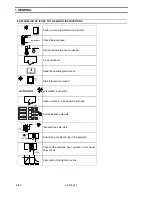
Page 5: ... water quick release coupling aqua dest I Unit ON 0 Unit OFF des start stop Disinfection mode key operated switch des Marks information for higher surface temperature in the disinfection mode Overtemperature protection temperature limit controller Selection of switching interlocking functions i Error code enquiry acknowledgment of acoustic signal control Change switching functions activated displa...

Page 6: ... instructions des start stop 1 sec Start disinfection routine auto start automatical auto start 30 s Open unit doors for at least 30 seconds 2 2 U Set the desired setpoints 5 s start stop auto start activate the auto start auto start End of the auto start bring in the samples 30 s Take out the samples open unit doors for at least 30 seconds 180 C t Flow chart of disinfection routine 1 GENERAL 6 43...

Page 7: ...ent parts or file a complaint please state the data on the nameplate and if applicable the fault code Equipment log book We advise you to keep an equipment log book Keep a record of inspections and testing calibration work and any major work carried out on the unit such as maintenance agents loaded etc in this log book refer to APPENDIX Operating instructions The operator employer is expected to p...

Page 8: ... clinics and hospitals Laboratories operating at safety levels L1 L2 and L3 Only organisms which comply with the requirements for safety levels L1 L2 and L3 may be handled in the unit The unit must be set up and operated in accordance with all applicable regulations in your country FRG ZH 1 119 ZH 1 342 ZH 1 343 ZH 1 598 It is not permitted to handle gases or agents whose vapours are combustible o...

Page 9: ...essary inspections maintenance and repair work are carried out by Heraeus Service Department personnel or by personnel authorized by our company Gas is to be supplied to each unit by means of a pressure reducer with the inlet pressure set to between 0 8 and max 1 bar This setting must not be changed for safety reasons FRG ZH 1 119 The place of installation must be thoroughly ventilated in order to...

Page 10: ...it on a solid non flammable surface laboratory tables subframes Make sure that the unit is in a stable and perfectly upright position Do not cover or obstruct the fresh air or exhaust vents in the unit housing please observe the minimum clearances see page 11 CO2 are admitted into the gassed incubator CO2 is a health risk hazard The place of installa tion must therefore be well ventilated Gases di...

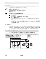
Page 11: ...or to connecting the unit to the mains make sure that the power supply ratings match those stated on the nameplate Your unit is equipped with a power supply cable with a grounding contact type plug Fuse protection required Use a type G 16 circuit break switch or a type T 16 A fusible cutout Refer to the Chapter titled TECHNICAL SPECIFICATIONS for unit power consumption 4 SETUP AND INSTALLATION 50 ...

Page 12: ...l set the nominal value to 21 0 average oxygen content of ambient atmosphere RS 232 interface Serial interface for computer aided acquisition and documentation of critical operating parameters temperature CO2 relative humidity error codes etc The RS 232 interface can connect a single unit in combination with the Kelvilog software package and can be expanded to connect 31 units with the Netcontrol ...

Page 13: ...nnection to the gas supplies CO2 O2 or rather N2 are located on the rear panel of the incuba tor The CO2 content of the atmosphere in the chamber can be regulated in the range 0 to 20 The O2 concentration inside the unit can be regulated in the range 3 to 90 O2 by admit ting N2 21 O2 or O2 21 O2 The sum of the nominal values for CO2 O2 must not exceed 90 Example 10 CO2 80 O2 90 possible 20 CO2 80 ...

Page 14: ...rranged inside the units The sup port can be offset in the carrier racks at intervals of 46 mm Six piece gas tight glass screen By virtue of the small vent cross section unnecessary cooling and discharge of the atmosphere in the chamber is largely avoided when a glass door is opened of the six piece gas tight glass screen Lockable outside door The outside door is lockable Disinfection routine This...

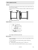
Page 15: ... Master Switch 4 Vent overflow Water supply 5 Level gauge Water supply 6 Setting knob Temperature protection device 7 Press button Disinfection mode 8 Master switch 9 Quick release coupling Add drain water Fig 4 Switch panel 6 OPERATE 50 079 041 15 45 max min autozero des aqua dest 2 Duto start control L des start stop 1 2 3 4 5 6 7 9 A 8 U 2 Heraeus ...

Page 16: ...anister on the bracket lo cated on the upper left of the incubator fig 1 Connect the tubing connector fig 1 into the quick fit coupling the water reservoir will be filled under the force of gravity Should the water not flow there may be an airlock in the tube in which case press on the tube bulb to move the air through Attention If the reservoir is overfilled the excess water any will flow from th...

Page 17: ...loor and connect it using the quick release coupling 9 Take care that the filling canister does not overflow Disconnect the quick release coupling if necessary Always drain the water reservoir before transporting the unit Mains switch 0 I Unit OFF Unit ON the green indicator lamp 3 indicates that unit is ready for operation Fig 5 Mains switch 8 6 OPERATE 50 079 041 17 45 ...

Page 18: ...Temperature Limit Controller to the required value depending on the max cutout temperature If the Temperature Limit Controller is set to the upper temperature limit it assumes the function of unit protection protection of unit and surroundings If the Temperature Limit Controller is set to approx 2 C above the nominal temperature set at the temperature controller it assumes the function of load pro...

Page 19: ...GASSING optional 15 Key O2 setpoint optional 6 Display O2 concentration optional 16 Key Relative humidity setpoint 7 Indicator lamp HUMIDIFICATION 17 Indicator lamp auto start 8 Display Relative humidity 18 Key Error code inquiry Start calibration routines 9 Key Increase reading 19 Indicator lamp Control 10 Key Decrease reading 20 Key Switching functions 6 OPERATE 50 079 041 19 45 2 3 4 5 6 7 1 17...

Page 20: ...temperature set point C release Temperature inside unit is dis played Setting the CO2 setpoint Instruction Entry Keys Remarks Display Remarks Status Display CO2 setpoint CO2 press Actual setpoint is displayed and decimal point flashes Select CO2 setpoint CO2 drücken Setpoint increases CO2 drücken Setpoint decreases Adopt NEW CO2 setpoint CO2 release CO2 concentration inside unit is displayed Setti...

Page 21: ...lay Remarks Status Open the unit door for at least 30 seconds All displays flash Remove samples and vessels from the interior of the unit Activate the disinfection rou tine turn key in direction of arrow des start stop Indicator Lamp page 19 11 flashes and indicator lamp page 15 2 comes on Press for approx 1 second Close the door Disinfection routine runs automati cally Temperature Limit Controlle...

Page 22: ...or lamp des as soon as the unit reaches the set operating temperature e g 37 0 C is reached The sensors are automatically calibrated auto start and the unit is readjusted to the set gas rel humidity setpoints The disinfection routine is completed If a temperature of 200 C is exceeded during the disinfection routine the latter is cancelled and all poles of the heating system are disconnected Error ...

Page 23: ...0 Activate auto start Indicator lamp page 19 17 auto start flashes Press for approx 5 seconds Close all unit doors Temperature reads Actual value CO2 reads 0 0 O2 reads 21 0 optional rel humidity reads Actual value The unit is set to the temperature and relative humidity setpoints When temperature and relative hu midity setpoints are achieved consistently the CO2 measuring system is automatically ...

Page 24: ...ror code request The unit is equipped with an error diagnosis system This diagnosis system lets you detect and evaluate a fault during operation by means of specific codes If an error occurs within a control loop the relevant display flashes to indicate this Press page 19 18 to display the error detected by the diagnosis system and to acknowl edge the alarm When the error is cleared the error mess...

Page 25: ...e Refer to page 12 204 CO2 CO2 measuring cell faulty Sensor broken short circuited Contact the service department of Thermo Electron Gmbh 300 N 2 N2 below setpoint Actual O2 value setpoint 2 Gassing with N2 Check the gas supply for gas cylinder content inlet pressure supply line and connection to unit Refer to page 13 14 301 N 2 N2 above setpoint Actual O2 value setpoint 2 Begasung mit N2 Check th...

Page 26: ... for error codes 101 201 They can also be displayed after a setpoint is decreased Example When operating the unit with the setpoint entered for 10 CO2 If the CO2 setpoint is decreased to 5 CO2 the unit cannot reach this lower CO2 concentration quickly enough due to its tightness Error 201 is displayed The designated error messages are displayed when Setpoint actual value Setpointtemperatur ambient...

Page 27: ... Instruction Entry Keys Remarks Display Remarks Status Select function level 1 Press Indicator lamp control flashes and current function level is indi cated by a flashing display or Press C Circuit status display and factory setting Acoustic alarm ON Release and press again C CO2 Change circuit status acoustic alarm OFF Press C CO2 Change circuit status acoustic alarm ON Press C CO2 Exit function ...

Page 28: ...by the flashing display or Press C Display circuit status factory setting Humidification ON Release and press again C CO2 Change circuit status Humidification OFF Press C CO2 Change circuit status Humidification ON Press C CO2 Exit function level Press Actual temperature CO2 O2 and rel humidity values are displayed again after 1 minute Press any setpoint key Actual temperature CO2 O2 and rel humid...

Page 29: ...n Example Display 5 0 CO2 Comparative measurement 4 2 CO2 Instruction Entry Keys Remarks Display Remarks Status Select function level 3 Hold down Indicator lamp control flashes and the current function level is indi cated on the flashing display or Press C Display zero point Release and press again C CO2 Enter determined CO2 con centration or Press C CO2 Start calibration process exit function lev...

Page 30: ...ion level 4 Hold down Indicator lamp control flashes and current function level is indicated by flashing display or Press C Display circuit status factory setting setpoints released Release and hold down again C CO2 Change circuit status locked setpoints Press C CO2 Change circuit status Release setpoints Press C CO2 Exit function level Release Actual temperature CO2 O2 and rel humidity values are...

Page 31: ...s Status Select function level 5 Hold down Indicator lamp control flashes and the current function level is indi cated by the flashing display or Press C Display circuit status factory setting Door heater ON Release and hold down again C CO2 Change circuit status Door heater OFF Press C CO2 Change circuit status Door heater ON Press C CO2 Exit function level Release Actual temperature CO2 O2 and r...

Page 32: ... protection de vice Adjust Temperature Limit Control ler 6 Refer to page 18 Select switching function s as required On control and display panel refer to page 20 and 27 to 31 Activate auto start Press Indicator lamp auto start flashes Hold down for approx 5 seconds Close all unit doors Temperature displays actual value CO2 displays 0 0 O2 displays 21 0 rel humidity displays actual value auto start...

Page 33: ...t loading determines the temperature conditions in the chamber If large objects or auxiliaries are placed inside the chamber this can impair the temperature distribution in the unit When loading the unit do not arrange articles too close to one another on the shelves use only approx 70 of surface area in order to avoid impairing air circulation and en sure constant heat flow Do not impair temperat...

Page 34: ...ion after shutdown Shut off the gas supply Remove disinfect and clean any objects or auxiliaries put into the unit Disinfect and clean the chamber Leave the unit doors open until the chamber is dry Disinfect the unit with hot air disinfection routine Set the mains switch to 0 and disconnect the power plug 9 SHUTDOWN 34 43 50 079 041 ...

Page 35: ...ls e g screw driver and detach them by lifting it up Clean inner housing shelves and carrier racks using a warm skin sensitive detergent Pril and allow them to dry completely Do not wet sensors 4 6 8 with liquids and disinfectants 1 Lead through and pressure compensation vent 2 Steam outlet Do not fill unit with any liquids only clean the surface 3 Recirculated air blower 4 O2 sensor optional 5 Pt...

Page 36: ...te prior to loading Testing The serviceability and safety of the unit are only guaranteed if the necessary testing maintenance and repair work is carried out by the Thermo Electron Gmbh department or by staff authorized by us The unit should be checked for safety leakproofing and serviceability at least once a year Equipment log book We recommend you keep an equipment log book refer to APPENDIX Ke...

Page 37: ...25 445 Gasket for iner casing front 50 048 705 Glass door for gas tight glass screen left 50 030 020 Glass door for gas tight glass screen with feed trough left 50 030 021 Glass door for gas tight glass screen right 50 030 022 Seal for glass door for gas tight glass screen 50 041 536 Filler canister 50 029 126 Equipment fuse T 6 3 A slow blow 2 pcs 03 002 641 Sealing plug for feed through without ...

Page 38: ...deviation temporal DIN 12 880 Part 2 K 0 1 Temperature deviation at 37 C spatial DIN 12 880 Part 2 50 C K K 0 5 0 7 Heating up time with auto start ambient temperature 22 C unit empty to 37 C h approx 5 Cooling time ambient temperature 22 C unit empty from 37 C to 25 C h approx 5 Heat release into surroundings at 37 C 95 rel humidity Heat release into surroundings at 50 C 95 rel humidity Heat rele...

Page 39: ... 60 50 60 Radio interference suppression DIN VDE 0875 Interference suppression level N Type of enclosure DIN 40050 IP 20 Protection class I Overvoltage category IEC 1010 II Degree of soiling IEC 1010 2 Rated current A 5 2 or 10 0 Fuse protection Fuse Circuit break switch T 16 A slow blow G 16 Rated power consumption during incubation disinfection kW 1 2 1 2 MISCELLANEOUS Sound pressure level DIN 4...

Page 40: ...oated in various plas tics partly mounted on printed circuit boards bonded with epoxy resin Disposal WEEE Compliance This product is required to comply with the European Union s Waste Electrical Electronic Equipment WEEE Directive 2002 96 EC It is marked with the following symbol Thermo Electron Corporation has contracted with one or more recycling disposal companies in each EU Member State and th...

Page 41: ...of BBD 6220 gassed incubator Gas consumption corresponds to the gas quantity re leased at the back of the unit which has to be discharged safely into the outside air by ventilating the placement area 14 GAS CONSUMPTION 50 079 041 41 45 ...

Page 42: ...lture media Dependency on the CO2 concentration 6 8 7 7 2 7 4 7 6 0 2 4 6 8 10 12 14 16 18 pH value CO2 Media Na HCO3 g l DMEM 3 70 BME 2 20 MEM 2 20 Medium 199 2 20 Mc Coy 2 20 F 10 1 20 F 12 1 20 MEM 0 85 Media with Hanks Salts 0 35 3 70 2 20 1 20 0 85 0 35 ...

Page 43: ...basic rules regarding the handling of pathogenes Disinfect all workplaces on a daily basis It may be necessary to switch disinfectants as a precaution against resistant germs Do not wear protective garments outside the working areas Contaminated equipment must be autoclaved or disinfected prior to cleaning Waste containing pathogenes must be collected safely and rendered harmless through autoclavi...

Page 44: ...ogical agents may only be handled with approval under the terms of the Federal Epidemics Act Approval under the terms of the Federal Animal Epidemics Act and the Ordinance concerning Agents of Animal Epidemics is required to handle agents of animal epidemics Pregnant women or nursing mothers are not permitted to handle infectious and human pathogenic biological agents or materials containing these...

Page 45: ...Internet www thermo com 50 079 041 45 45 ...

Reviews: