Service Instructions Safety Cabinet HERAsafe KS / KSP
Service Instructions Safety Cabinet HERAsafe KS / KSP
24
24
4
4
.
.
M
M
e
e
d
d
i
i
a
a
c
c
o
o
n
n
n
n
e
e
c
c
t
t
i
i
o
o
n
n
s
s
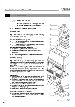
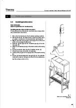
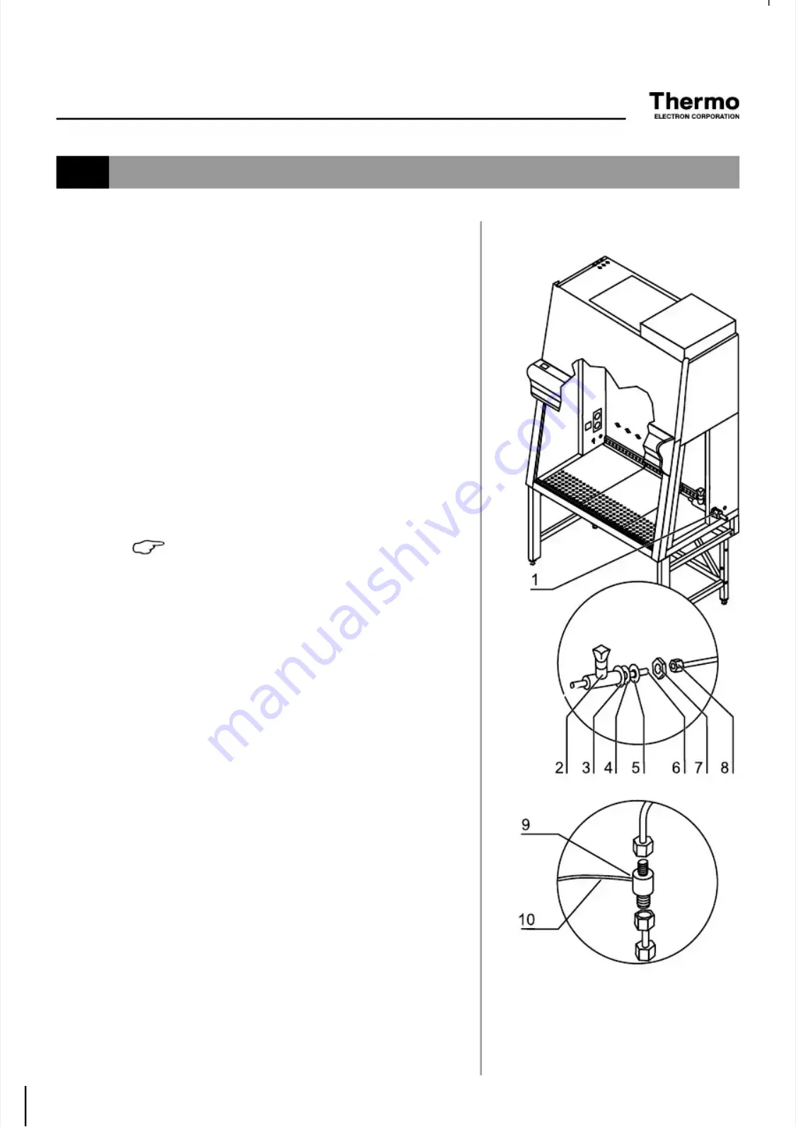
Installing media valves to the sidewall:
Installing media valves to the sidewall:
Fig. 8:
Fig. 8:
The media valves are installed to the preinstalled lead-
The media valves are installed to the preinstalled lead-
ins [1].
ins [1].
1.
1. Move the
Move the front wi
front window to t
ndow to the maxi
he maximal open
mal opening posit
ing position.
ion.
2.
2. Switch
Switch the devic
the device off, di
e off, disconnect
sconnect it from
it from the power s
the power supp-
upp-
ly system, and protect it from accidental reconnection.
ly system, and protect it from accidental reconnection.
3.
3. Remove
Remove the plug
the plug from th
from the sidewa
e sidewall lead-
ll lead-in or rem
in or remove the
ove the
plug and disconnect the PG screw connection.
plug and disconnect the PG screw connection.
4.
4. Slid
Slide the gask
e the gasket [4] an
et [4] and the beze
d the bezel [3] ont
l [3] onto the thre
o the threaded pi
aded pipe
pe
of the media valve [2].
of the media valve [2].
5.
5. From t
From the inside
he inside of the sa
of the sample cham
mple chamber,
ber, push the
push the media
media
valve through the lead-in.
valve through the lead-in.
6.
6. From th
From the outsi
e outside, slid
de, slide the other gas
e the other gasket [5] onto th
ket [5] onto the threa-
e threa-
ded pipe of the media valve.
ded pipe of the media valve.
7.
7. Secur
Secure the medi
e the media valve to t
a valve to the side
he sidewall le
wall lead-in us
ad-in using the nu
ing the nutt
[7].
[7].
8.
8. Connect
Connect the mead
the meadia supply
ia supply line usi
line using a unio
ng a union nut [8].
n nut [8].
NOTE - Combustible gas
NOTE - Combustible gas
If combustible gas is to be supplied into the
If combustible gas is to be supplied into the
sample chamber, the media valve solenoid
sample chamber, the media valve solenoid
must be integral to the device
must be integral to the device control. The gas
control. The gas
supply is controlled in a way that the gas sup-
supply is controlled in a way that the gas sup-
ply is activated when the
ply is activated when the device is operational.
device is operational.
The annex of these service instructions con-
The annex of these service instructions con-
tains wiring diagrams for integrating the sole-
tains wiring diagrams for integrating the sole-
noid into the device control.
noid into the device control.
Installing the solenoid:
Installing the solenoid:
The solenoid is installed externally, either to the
The solenoid is installed externally, either to the sidewall supply
sidewall supply
line or to the supply lines at the device ceiling.
line or to the supply lines at the device ceiling.
1.
1. Instal
Install the
l the solenoid
solenoid [9] int
[9] into the s
o the supply
upply line.
line.
2.
2. Connnec
Connnect the con
t the connecting
necting cables
cables [10] to th
[10] to the devic
e device control
e control
(see wiring diagrams in the annex).
(see wiring diagrams in the annex).
Fig. 8,
Fig. 8,
UV connection
UV connection
Installing media valves to the
Installing media valves to the
sidewall
sidewall
Summary of Contents for HERAsafe KS
Page 118: ...117 117 ...

