Service Instructions Safety Cabinet HERAsafe KS / KSP
Service Instructions Safety Cabinet HERAsafe KS / KSP
43
43
Fig. 29,
Fig. 29,
Gas strut removal
Gas strut removal
1
1
2
2
.
.
F
F
r
r
o
o
n
n
t
t
d
d
o
o
o
o
r
r
c
c
o
o
m
m
p
p
o
o
n
n
e
e
n
n
t
t
s
s
12
12.2
.2
Re
Repl
pla
aci
cin
ng t
g th
he g
e ga
as s
s str
tru
utts
s
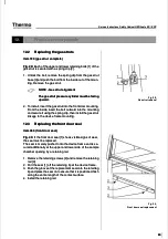
Item 720 (gas strut complete)
Item 720 (gas strut complete)
Fig. 29:
Fig. 29:
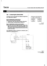
Each of the upper and lower retaining bolts [1] of the
Each of the upper and lower retaining bolts [1] of the
gas strut is secured with a spring clip [2].
gas strut is secured with a spring clip [2].
1.
1. Unlock t
Unlock the bolt, r
he bolt, remove th
emove the spring c
e spring clip from
lip from the gas s
the gas strut
trut
base [3] and push the bolt from the inside out of the moun-
base [3] and push the bolt from the inside out of the moun-
ting. Remove the gas strut.
ting. Remove the gas strut.
NOTE - Gas strut alignment
NOTE - Gas strut alignment
The gas strut pressure cylinder must be facing
The gas strut pressure cylinder must be facing
upward.
upward.
2.
2. T
To instal
o install, insert the gas str
l, insert the gas strut into the front doo
ut into the front door mounting
r mounting..
From the inside, insert the bolt outward into the mounting
From the inside, insert the bolt outward into the mounting
and secure it using the spring clip, then install the gas strut
and secure it using the spring clip, then install the gas strut
linkage to the device frame mounting.
linkage to the device frame mounting.
12
12.3
.3
Re
Repl
plac
acin
ing t
g the
he fr
fron
ont d
t doo
oor s
r sea
eall
Item 360 (front door seal)
Item 360 (front door seal)
Fig. 30:
Fig. 30:
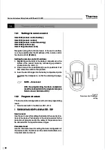
If the front door seal [1] shows visible signs of wear,
If the front door seal [1] shows visible signs of wear,
the seal must be replaced.
the seal must be replaced.
The seal is merely pushed onto the device frame and is se-
The seal is merely pushed onto the device frame and is se-
cured additionally at the upper and lower side of the sample
cured additionally at the upper and lower side of the sample
chamber opening by a retaining rail.
chamber opening by a retaining rail.
1.
1. Remo
Remove the ret
ve the retainin
aining screw
g screws [2] and rem
s [2] and remove the ret
ove the retainin
aining
g
rail [3].
rail [3].
2.
2. Pull the s
Pull the seal [1] of
eal [1] off the reta
f the retaining lip
ining lip at the devic
at the device frame.
e frame.
3.
3. Push th
Push the groove
e groove of the
of the replacem
replacement seal
ent seal onto the
onto the retaining
retaining
lip and press the seal on to ensure that it is positioned flush
lip and press the seal on to ensure that it is positioned flush
along the entire length of the contact surface.
along the entire length of the contact surface.
4.
4. Inst
Install t
all the re
he retai
taining
ning rail
rail..
Fig. 30,
Fig. 30,
Front door seal replacement
Front door seal replacement
Summary of Contents for HERAsafe KS
Page 118: ...117 117 ...


