background image

61

61


Service Instructions Safety Cabinet HERAsafe KS / KSP

Service Instructions Safety Cabinet HERAsafe KS / KSP

62

62

1

1

4

4

.

.

D

D

e

e

v

v

i

i

c

c

e  

e  

c

c

o

o

n

n

t

t

r

r

o

o

l  

l  

p

p

r

r

o

o

g

g

r

r

a

a

m

m

m

m

i

i

n

n

g

g

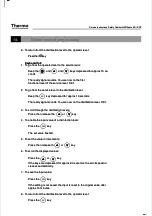
D421

D421

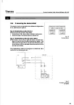
, for example, breaks down as follows:

, for example, breaks down as follows:

In accordance with the factory setting

In accordance with the factory setting

(D)

(D)

, a safety 

, a safety cabinet 

cabinet  KS / K

KS / KSP 12

SP 12

 (4)

 (4)

 for

 for

the configuration identifier

the configuration identifier

21

21

 has the following switching states:

 has the following switching states:

P 03 = 1

P 03 = 1

P 04 = 0

P 04 = 0

P 05 = 1

P 05 = 1
P 06 = 0

P 06 = 0
P 07 = 1

P 07 = 1
P 08 = 1

P 08 = 1

Configuration identifier overview

Configuration identifier overview

IId

de

en

nttiiffiie

err

P

P0

03

3

P

P0

04

4

P

P0

05

5

P

P0

06

6

P

P0

07

7

P

P0

08

8

IId

de

en

nttiiffiie

err

P

P0

03

3

P

P0

04

4

P

P0

05

5

P

P0

06

6

P

P0

07

7

P

P0

08

8

0

01

1

1

1

1

1

1

1

1

1

1

1

1

1

3

33

3

0

1

0

1

1

1

1

1

1

1

1

1

0

02

2

1

1

1

1

1

1

1

1

1

0

1

0

3

34

4

0

1

0

1

1

1

1

1

1

0

1

0

0

03

3

1

1

1

1

1

1

1

1

0

1

0

1

3

35

5

0

1

0

1

1

1

1

1

0

1

0

1

0

04

4

1

1

1

1

1

1

1

1

0

0

0

0

3

36

6

0

1

0

1

1

1

1

1

0

0

0

0

0

05

5

1

1

1

1

1

0

1

0

1

1

1

1

3

37

7

0

1

0

1

1

0

1

0

1

1

1

1

0

06

6

1

1

1

1

1

0

1

0

1

0

1

0

3

38

8

0

1

0

1

1

0

1

0

1

0

1

0

0

07

7

1

1

1

1

1

0

1

0

0

1

0

1

3

39

9

0

1

0

1

1

0

1

0

0

1

0

1

0

08

8

1

1

1

1

1

0

1

0

0

0

0

0

4

40

0

0

1

0

1

1

0

1

0

0

0

0

0

0

09

9

1

1

1

1

0

1

0

1

1

1

1

1

4

41

1

0

1

0

1

0

1

0

1

1

1

1

1

1

10

0

1

1

1

1

0

1

0

1

1

0

1

0

4

42

2

0

1

0

1

0

1

0

1

1

0

1

0

1

11

1

1

1

1

1

0

1

0

1

0

1

0

1

4

43

3

0

1

0

1

0

1

0

1

0

1

0

1

1

12

2

1

1

1

1

0

1

0

1

0

0

0

0

4

44

4

0

1

0

1

0

1

0

1

0

0

0

0

1

13

3

1

1

1

1

0

0

0

0

1

1

1

1

4

45

5

0

1

0

1

0

0

0

0

1

1

1

1

1

14

4

1

1

1

1

0

0

0

0

1

0

1

0

4

46

6

0

1

0

1

0

0

0

0

1

0

1

0

1

15

5

1

1

1

1

0

0

0

0

0

1

0

1

4

47

7

0

1

0

1

0

0

0

0

0

1

0

1

1

16

6

1

1

1

1

0

0

0

0

0

0

0

0

4

48

8

0

1

0

1

0

0

0

0

0

0

0

0

1

17

7

1

0

1

0

1

1

1

1

1

1

1

1

4

49

9

0

0

0

0

1

1

1

1

1

1

1

1

1

18

8

1

0

1

0

1

1

1

1

1

0

1

0

5

50

0

0

0

0

0

1

1

1

1

1

0

1

0

1

19

9

1

0

1

0

1

1

1

1

0

1

0

1

5

51

1

0

0

0

0

1

1

1

1

0

1

0

1

2

20

0

1

0

1

0

1

1

1

1

0

0

0

0

5

52

2

0

0

0

0

1

1

1

1

0

0

0

0

2

21

1

1

0

1

0

1

0

1

0

1

1

1

1

5

53

3

0

0

0

0

1

0

1

0

1

1

1

1

2

22

2

1

0

1

0

1

0

1

0

1

0

1

0

5

54

4

0

0

0

0

1

0

1

0

1

0

1

0

2

23

3

1

0

1

0

1

0

1

0

0

1

0

1

5

55

5

0

0

0

0

1

0

1

0

0

1

0

1

2

24

4

1

0

1

0

1

0

1

0

0

0

0

0

5

56

6

0

0

0

0

1

0

1

0

0

0

0

0

2

25

5

1

0

1

0

0

1

0

1

1

1

1

1

5

57

7

0

0

0

0

0

1

0

1

1

1

1

1

2

26

6

1

0

1

0

0

1

0

1

1

0

1

0

5

58

8

0

0

0

0

0

1

0

1

1

0

1

0

2

27

7

1

0

1

0

0

1

0

1

0

1

0

1

5

59

9

0

0

0

0

0

1

0

1

0

1

0

1

2

28

8

1

0

1

0

0

1

0

1

0

0

0

0

6

60

0

0

0

0

0

0

1

0

1

0

0

0

0

2

29

9

1

0

1

0

0

0

0

0

1

1

1

1

6

61

1

0

0

0

0

0

0

0

0

1

1

1

1

3

30

0

1

0

1

0

0

0

0

0

1

0

1

0

6

62

2

0

0

0

0

0

0

0

0

1

0

1

0

3

31

1

1

0

1

0

0

0

0

0

0

1

0

1

6

63

3

0

0

0

0

0

0

0

0

0

1

0

1

3

32

2

1

0

1

0

0

0

0

0

0

0

0

0

6

64

4

0

0

0

0

0

0

0

0

0

0

0

0

Summary of Contents for HERAsafe KS

Page 1: ...Safety Cabinet HERAsafe KS KSP Safety Cabinet HERAsafe KS KSP Service Instructions Service Instructions Valid 03 2006 50077494 D Valid 03 2006 50077494 D ...

Page 2: ...ofThermoElectronLED GmbH ofThermoElectronLED GmbH This regulation does not apply to reproductions for in plant use This regulation does not apply to reproductions for in plant use Trademarks Trademarks HERAsafe HERAsafe and Heraeus are registered trademarks of Thermo Electron LED and Heraeus are registered trademarks of Thermo Electron LED GmbH All other trademarks mentioned in the service instruc...

Page 3: ...dia val valves ves opt optiona ional a l at the t the sam sample ple chamber chamber rear rear panel panel 21 21 4 2 4 2 Inst Install allatio ation po n point ints a s at th t the s e samp ample le cham chamber ber side sidewall walls s 22 22 4 3 4 3 Inst Install alling ing med media ia val valves ves 23 23 5 5 Lamp Lamps s 25 25 5 1 5 1 Rep Replaci lacing the lu ng the lumin minesc escent tub ent...

Page 4: ...3 53 14 3 1 14 3 1 Service level overview Service level overview 53 53 14 3 2 14 3 2 Service level Service level settings settings 55 55 14 4 14 4 Paramete Parameter levels r levels 57 57 14 4 1 14 4 1 Paramet Parameter level overvie er level overview w 57 57 14 4 2 14 4 2 Paramet Parameter level settings er level settings 59 59 14 4 3 14 4 3 Configuri Configuring the ng the switchi switching st n...

Page 5: ... closing edg ing edge e 92 92 A 1 A 11 1 Noise le Noise level test vel test 93 93 A 12 A 12 Lighting i Lighting intensity t ntensity test est 94 94 A 13 A 13 Vibrat Vibration ion test test 95 95 A 14 A 14 UV intensity test UV intensity test 96 96 A 15 A 15 Setting Setting the the monitori monitoring ng devices devices 96 96 A 15 1 A 15 1 Downflow Downflow velocity a velocity alarm value larm value...

Page 6: ...xhau haust filt st filter repl er replace aceme ment nt 35 35 Fi Fig 22 g 22 Do Downf wnflo low fil w filter r ter rep eplac lacem emen ent t 36 36 Fi Fig g 23 23 Pr Prefi efilte lter r rep repla lacem cement ent 37 37 Fi Fig 24 g 24 Ex Exhau haust bl st blowe ower rep r repla lacem cement ent 38 38 Fi Fig g 25 25 Do Downf wnflow low bl blowe ower r r repl eplac acem ement ent 39 39 Fi Fig g 26 26...

Page 7: ...9 DIN with EN 12469 DIN 12980 12980 89 89 Fi Fig A g A 9 9 Ai Airfl rflow ow pa patte ttern rn I I 91 91 Fig Fig A 10 A 10 Air Airflow pa flow patter ttern II n II 92 92 Fig Fig A 11 A 11 Nois Noise e lev level test el test 93 93 Fig Fig A12 A12 Ligh Lighting in ting intens tensity te ity test st 94 94 Fig Fig A13 A13 Vib Vibrati ration on test test 95 95 Fig Fig B B 1 1 Disi Disinfec nfection tio...

Page 8: ...e ubject to ch ct to change w ange witho ithout ut further notice further notice For tr For transl anslatio ations int ns into forei o foreign lan gn languag guages th es the Germ e German ver an version of t sion of these op hese ope e rating instructions is binding rating instructions is binding Shoul Should you enc d you encounte ounter probl r problems th ems that are no at are not deta t deta...

Page 9: ...ctron LED are used The use of other parts presents unknown hazards and must therefore be refrained from hazards and must therefore be refrained from ins inspect pections an ions and main d maintena tenance are pe nce are perfor rformed at th med at the speci e specified in fied interv tervals als a repe a repeat tes at test is co t is conduc nducted af ted after an ter any insp y inspecti ections ...

Page 10: ... o on t n th he d e dev evi ice ce Observe operating instructions switchbox ceiling Observe operating instructions switchbox ceiling Biohazard left front of device Biohazard left front of device or alternatively or alternatively Cytostatic agents left front of device Cytostatic agents left front of device T5A fusing for sample chamber outlets switchbox front T5A fusing for sample chamber outlets s...

Page 11: ...t installation right side of light dome 1 3 1 3 3 3 Ad Addi ditio tiona nal sy l symb mbol ols on s on th the d e devi evice ce EN EN ve versi rsion on Safety tested light dome Safety tested light dome 1 3 1 3 4 4 Ad Addi ditio tiona nal sy l symb mbol ols o s on t n the d he devi evice ce NS NSF v F ver ersio sion n NSF symbol light dome NSF symbol light dome ETL symbol light dome ETL symbol ligh...

Page 12: ...nents may be contaminated may be contaminated Always observe the hygiene regulations of the Always observe the hygiene regulations of the operator operator Prior to beginning service work cytostatic in Prior to beginning service work cytostatic in fectious or other toxic substances or residues fectious or other toxic substances or residues thereof must always be removed completely thereof must alw...

Page 13: ...rt up If safety devices were removed or disabled If safety devices were removed or disabled during repairs the unit must not be started up during repairs the unit must not be started up before the safety devices have been reinstal before the safety devices have been reinstal led and checked for proper operation led and checked for proper operation Before the unit is started up and operated a Befor...

Page 14: ...0A 0A 1 1 Fi Firs rst E t Edi diti tion on CAN CSA C22 2 No 1010 1 92 Rev 1997 02 01 CAN CSA C22 2 No 1010 1 92 Rev 1997 02 01 On Only K ly KS ve S versi rsion on NS NSF F AN ANSI 4 SI 49 20 9 2002 02 Europe Middle East Africa Europe Middle East Africa I IE EC C 6 61 10 01 10 0 1 1 E EN N 1 12 29 98 80 0 2 20 00 05 5 Onl Only KSP v y KSP versi ersion DI on DIN 1298 N 12980 1996 0 1996 Desi Design ...

Page 15: ...ion a broad range For the standard wipe spray disinfection a broad range disinfectant can be used disinfectant can be used Recommended product Barrycidal 36 or Microcide SQ Recommended product Barrycidal 36 or Microcide SQ 2 2 2 2 L Li is st t o of f r re eq qu ui ir re ed d t to oo ol ls s M Mu ul lt ti im me et te er r U U I I O Oh hm m A Al ll le en n k ke ey y s se et t 1 1 5 5 6 6 m mm m O Op...

Page 16: ...nserts 7 for the retaining screws 6 inserts 7 for the retaining screws 6 are preinstalled in the de are preinstalled in the de vice ceiling vice ceiling To install the supplementary filter KAEF additional holes must To install the supplementary filter KAEF additional holes must be drilled For hole dimensioning and positioning refer to be drilled For hole dimensioning and positioning refer to the t...

Page 17: ...system and protect it from accidental reconnection ly system and protect it from accidental reconnection 2 2 Thoro Thoroughly cl ughly clean the cont ean the contact surf act surfaces arou aces around the exhau nd the exhaust st aperture to ensure that they are absolutely grease and dust aperture to ensure that they are absolutely grease and dust free free 3 3 Secure t Secure the disin he disinfec...

Page 18: ...vel the dev l the device s ice see Sec ee Section 3 tion 3 7 7 3 3 5 5 H He ei ig gh ht t a ad dj ju us st ta ab bl le e r ra ac ck k KS version KS version Item 1350 plug for rack sidemembers Item 1350 plug for rack sidemembers The height of the height adjustable rack can be set The height of the height adjustable rack can be set within a ran within a ran ge of 680 880 mm ge of 680 880 mm 1 1 Fig ...

Page 19: ...g c ecting cables 2 ables 2 to the syn to the syn chronizer module 3 and to the electric motors 1 chronizer module 3 and to the electric motors 1 4 4 Place t Place the safet he safety cabine y cabinet onto the ra t onto the rack so that i ck so that it is secu t is secured red by the locating pins 8 Secure the housing to the rack by by the locating pins 8 Secure the housing to the rack by installi...

Page 20: ...t he mounting hole o ing hole of the floor f the floor pan pan 4 4 Slide t Slide the cone di he cone disk 6 on sk 6 onto the dra to the drain plug w in plug with the c ith the conical onical side facing upward side facing upward 5 5 Inst Install the nut 7 all the nut 7 to the drain p to the drain plug and tig lug and tighten it so tha hten it so that the t the drain plug seals at the floor drain p...

Page 21: ...e connection The connections have been designed for the on site connection of 3 8 threads of 3 8 threads The connections are suitable for the installation of laborato The connections are suitable for the installation of laborato ry fittings R 3 8 Upon delivery of ry fittings R 3 8 Upon delivery of the device the connections the device the connections are sealed with plugs and screwed on bezels are...

Page 22: ...fittings R 3 8 Upon delivery of the device the lead ins are capped tightly Upon delivery of the device the lead ins are capped tightly Application in USA Canada Application in USA Canada Interior plug and exterior safety glass screw connection Interior plug and exterior safety glass screw connection Application in EU Application in EU Exterior plug Exterior plug Distances at the side of the device...

Page 23: ... 7 Unscrew the plug from the supply line at the rear Unscrew the plug from the supply line at the rear panel of the sample chamber 9 panel of the sample chamber 9 4 4 Slide th Slide the gasket 6 e gasket 6 onto the t onto the threaded pi hreaded pipe 5 of th pe 5 of the me e me dia valve 7 dia valve 7 5 5 Wra Wrap the thre p the threaded pip aded pipe 5 of the m e 5 of the media va edia valve wit ...

Page 24: ...Secure the medi e the media valve to t a valve to the side he sidewall le wall lead in us ad in using the nu ing the nut t 7 7 8 8 Connect Connect the mead the meadia supply ia supply line usi line using a unio ng a union nut 8 n nut 8 NOTE Combustible gas NOTE Combustible gas If combustible gas is to be supplied into the If combustible gas is to be supplied into the sample chamber the media valve...

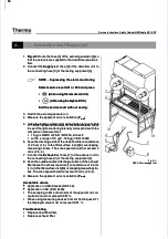
Page 25: ... s Items 440 450 luminescent tube sockets Items 440 450 luminescent tube sockets Fig 9 Fig 9 The sockets 7 of the luminescent tubes are secured The sockets 7 of the luminescent tubes are secured to the recesses 6 in the mounting frame by the retainers 8 to the recesses 6 in the mounting frame by the retainers 8 1 1 Switch Switch the devic the device off di e off disconnec sconnect it from t it fro...

Page 26: ...e power supply unit remove the power supply unit 7 7 Secure th Secure the new pow e new power suppl er supply unit t y unit to the mo o the mounting fr unting frame ame 8 8 Con Connec nect th t the wi e wirin ring g 9 9 Install Install the li the light do ght dome s me see Se ee Section ction 5 1 5 1 5 5 4 4 R Re ep pl la ac ci in ng g U UV V l la am mp ps s Item 100 UV lamp Item 100 UV lamp Item ...

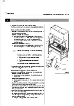
Page 27: ...tect it from accidental reconnection 3 3 Re Remo move t ve the U he UV la V lamp mp 4 4 Remo Remove the two re ve the two retain taining scre ing screws 2 of the i ws 2 of the insert be nsert bezel 4 zel 4 and slide the insert bezel out only so far that the power and slide the insert bezel out only so far that the power supply unit 5 is accessible supply unit 5 is accessible 5 5 Disconn Disconnect...

Page 28: ...re them to the holes 6 at the sidewall using the screws at the sidewall using the screws 9 9 Seal the Seal the joint be joint between si tween sidewall a dewall and outlet nd outlet using se using sealant alant 6 6 2 2 Re Repl pla aci cin ng t g the he d dis isin infe fec cti tion on a ada dap pte ter r Items 120 160 disinfection adapter Items 120 160 disinfection adapter Item 190 sealant Item 190...

Page 29: ... el l Item 740 display panel Item 740 display panel Fig 14 Fig 14 The display panel 1 is pushed onto bolts at the sample The display panel 1 is pushed onto bolts at the sample chamber rear panel and sealed with sealant chamber rear panel and sealed with sealant 1 1 Unl Unlock th ock the fron e front door a t door and tur nd turn it up n it up 2 2 Switch Switch the devic the device off di e off dis...

Page 30: ...surface must be dust and grease free 5 5 Att Attach the key ach the keyboard fo board foil to the fram il to the frame Conne e Connect the bus cab ct the bus cable le 2 to the receptacle 3 at the auxiliary PCB 2 to the receptacle 3 at the auxiliary PCB 6 6 Install Install the li the light d ght dome ome see S see Section ection 5 1 5 1 7 7 4 4 R Re ep pl la ac ci in ng t g th he p e pi il lo ot s ...

Page 31: ...window window rearward o rearward out of the ut of the sidemem sidemember bevel ber bevel 8 8 Clean Clean the sid the sidemember ememberand hous and housing fram ing frame edges e edgesthoroughly thoroughly and remove any sealant residues The contact surfaces of and remove any sealant residues The contact surfaces of the glass window must be grease and dust free the glass window must be grease and...

Page 32: ...ust only be carried out by the Tech nical Service of Thermo Electron LED or by nical Service of Thermo Electron LED or by specially trained and authorized service per specially trained and authorized service per sonnel sonnel NOTE Certificate of nonobjection NOTE Certificate of nonobjection If disposal of the device is delegated to a third If disposal of the device is delegated to a third party th...

Page 33: ...oles 4 at the panel front end wit el front end with h the locating pins 3 the locating pins 3 3 3 Secure t Secure the perfora he perforated pan ted panel to the el to the threaded threaded bushings bushings 6 6 of the panel retainers using the two screws 2 of the panel retainers using the two screws 2 9 9 3 3 Re Remo movi vin ng g i in ns st ta all llin ing th g the pl e ple enu num c m cov over e...

Page 34: ...er 1 1 Remove t Remove the workpl he workplate s fr ate s from the sa om the sample cha mple chamber mber 2 2 Fig 20 Fig 20 Have a suited disposal container 4 for the con Have a suited disposal container 4 for the con taminated coarse filter ready taminated coarse filter ready 3 3 Remove t Remove the coarse he coarse filter 3 filter 3 from it from its mounti s mounting bracket ng bracket 5 5 and s...

Page 35: ...le haust plenum fra num frame susp me suspends from ends fromthe devi the device ceili ce ceiling ng on four threaded rods 3 Loosen the threaded rod wing nuts on four threaded rods 3 Loosen the threaded rod wing nuts so that the frame is slightly lowered so that the frame is slightly lowered 5 5 Dis Disconn connect ect the the air air hose hose 6 6 Pull the Pull the downflow downflow plenum plenum...

Page 36: ...forward and discard it properly 5 5 Insert the Insert the new filt new filter so that t er so that the side wi he side with the fil th the filter descr ter descrip ip tion is visible Check to see if the filter gasket is OK tion is visible Check to see if the filter gasket is OK 6 6 Install Install the pressu the pressure profile re profiles and se s and secure them cure them using the using the re...

Page 37: ...the r o remove the remainin emaining prefilter e g prefilter element lements press the re s press the re taining clips out of the floorpan recess and lift the prefilter taining clips out of the floorpan recess and lift the prefilter elements out of the floorpan elements out of the floorpan 4 4 Seal the f Seal the filter plat ilter plate opening ti e opening tightly usi ghtly using foil and ng foil...

Page 38: ...g in the con n the control box trol box and remo and remove ve it from the control box it from the control box 4 4 Remove Remove the two ret the two retaining sc aining screws 3 rews 3 and remov and remove the ex e the ex haust blower from the exhaust plenum housing 4 haust blower from the exhaust plenum housing 4 5 5 Install Install the exhau the exhaust blower st blower 1 into 1 into the exhaus ...

Page 39: ... 5 tions 9 4 9 5 5 5 Swivel Swivel the down the downflow pl flow plenum upw enum upward rem ard remove the ove the four re four re taining screws 5 from the threaded taining screws 5 from the threaded sleeves 4 and remove sleeves 4 and remove the blower crossmember assembly from the plenum the blower crossmember assembly from the plenum 6 6 Secur Secure the new blo e the new blower to the cr wer t...

Page 40: ... The pres The pressure sens sure sensors are ors are merely merely inserted inserted into the into the moun moun ting 3 and must be lifted for removal ting 3 and must be lifted for removal 4 4 Insert the Insert the new pressu new pressure sensor re sensor sensor int sensor into the mou o the mounting nting connect the exhaust air hose 6 to the connecting sleeve connect the exhaust air hose 6 to th...

Page 41: ...Lowe Lower the fro r the front win nt window al dow all the wa l the way y 2 2 Switch Switch the devic the device off di e off disconnec sconnect it from t it from the power the power supp supp ly system and protect it from accidental reconnection ly system and protect it from accidental reconnection 3 3 Remove Remove the front the front door beze door bezel and t l and the plenum he plenum cover ...

Page 42: ... devi he device fram ce frame and push t e and push the two he two hinge bolts from the inside out into the hinge hinge bolts from the inside out into the hinge 2 2 Secure t Secure the hinge he hinge bolts o bolts on both si n both sides usin des using the cir g the circlips clips 3 3 Instal Install the l the front w front window indow see S see Section ection 12 2 12 2 4 4 Instal Install the l th...

Page 43: ...ll the gas strut and secure it using the spring clip then install the gas strut linkage to the device frame mounting linkage to the device frame mounting 12 12 3 3 Re Repl plac acin ing t g the he fr fron ont d t doo oor s r sea eal l Item 360 front door seal Item 360 front door seal Fig 30 Fig 30 If the front door seal 1 shows visible signs of wear If the front door seal 1 shows visible signs of ...

Page 44: ...th screws to the frame and to the lower crossmem ber see Fig 25 29 ber see Fig 25 29 4 4 Rem Remove the cr ove the cross ossmem member se ber see Fig e Fig 29 29 5 5 F Fi ig g 31 31 Remove the retaining screws 1 and remove the Remove the retaining screws 1 and remove the latch latch 6 6 Connect Connect the conn the connecting ecting cable t cable to the n o the new latc ew latch h 7 7 Posi Positio...

Page 45: ...e accidental separation of the To prevent the accidental separation of the front window from the frame the window must front window from the frame the window must be supported from below before the two cable be supported from below before the two cable rateiners are removed rateiners are removed 7 7 Fig 34 Fig 34 Remove the cable retainers 2 on both sides of Remove the cable retainers 2 on both si...

Page 46: ...de with other so that the front window may collide with other components components WARNING High voltage WARNING High voltage Contact with current carrying components may Contact with current carrying components may cause a lethal electric shock cause a lethal electric shock To test the traveling motions the device must To test the traveling motions the device must be connected to the power supply...

Page 47: ...ts points 3 3 Fig 36 Fig 36 Upon closing contact traveling motion stops the Upon closing contact traveling motion stops the left and right bearings 1 must be seated completely in the left and right bearings 1 must be seated completely in the recesses of the upper guide rails 2 installed to the ple recesses of the upper guide rails 2 installed to the ple num cover panel num cover panel 4 4 Check th...

Page 48: ...t the m wist the metallic t etallic tabs 2 abs 2 using pliers to release them from the recesses in the mo using pliers to release them from the recesses in the mo tor mounting bracket tor mounting bracket 7 7 The lef The left and righ t and right cables t cables of the fro of the front window nt window are secur are secured ed with screws 14 in the reel To remove the cable remove with screws 14 in...

Page 49: ...ct the ect the connector connector 6 from 6 from the bat the battery tery 4 4 Conn Connect the co ect the connec nnector to the ne tor to the new batt w battery ery r re ed d b bl la ac ck k 5 5 Sec Secure the b ure the batte attery wit ry with the cl h the clamp amp 6 6 Instal Install the l the light light dome dome see see Section Section 5 1 5 1 NOTE Retrofitting kit NOTE Retrofitting kit The p...

Page 50: ... t ith two po wo power s wer suppl upply uni y units ts 3 and 4 3 and 4 KS 9 KS 9and K and KS 12 S 12 are o are operat perated wi ed with on th one pow e power su er supply pplyunit unit 7 7 The face of the control box has an RS 232 connector 5 and The face of the control box has an RS 232 connector 5 and the two fuses 6 for the device integral power supply the two fuses 6 for the device integral ...

Page 51: ... del e delive ivers ex rs exhaus haust air t air Fig 41 Potential free contact monitor alarm Fig 41 Potential free contact monitor alarm When failures occur in the air system circuits an alarm mes When failures occur in the air system circuits an alarm mes sage is issued to the connected monitoring system This sage is issued to the connected monitoring system This external alarm signal that is con...

Page 52: ...y on and press the lid slightly on so that the retaining clip enga so that the retaining clip enga ges ges NOTE Value reset NOTE Value reset After the programming has been completed After the programming has been completed reset the code switch to the reset the code switch to the original value see original value see Service Level Submenu S12 Service Level Submenu S12 1 14 4 2 2 P Pr ro og gr ra a...

Page 53: ...o om mi in na al l v va al lu ue e f fo or r e ex xh ha au us st t b bl lo ow we er r 1 1 1 10 00 0 S Se et tt ti in ng g s se ee e S Se ec ct ti io on n A A S S0 03 3 S Se et t d do ow wn nf fl lo ow w v ve el lo oc ci it ty y a al la ar rm m l li im mi it t 1 1 1 10 00 0 S Se et tt ti in ng g s se ee e S Se ec ct ti io on n A A S S0 05 5 S Se et t i in nf fl lo ow w v ve el lo oc ci it ty y a al...

Page 54: ...7 7 1 10 00 01 1 S S7 7 S S6 6 S S1 11 1 0 00 01 10 0 F Fu un nc ct ti io on n i is s c co or rr re ek kt t 1 10 01 10 0 S S6 6 S S1 11 1 0 00 01 11 1 S S7 7 0 00 00 00 0 S S2 2 S S3 3 0 00 00 01 1 S S2 2 S S3 3 S S7 7 1 10 00 00 0 S S2 2 S S3 3 S S6 6 S S1 11 1 1 10 00 01 1 S S2 2 S S3 3 S S7 7 S S6 6 S S1 11 1 1 10 01 11 1 S S7 7 S S6 6 S S1 11 1 0 00 01 11 1 F Fu un nc ct ti io on n i is s c co...

Page 55: ...re now on the first The ready signal sounds You are now on the first functional level of the service level S 01 functional level of the service level S 01 2 2 T To scro o scroll th ll through s rough service ervice levels levels Press then release the Press then release the or or key key 3 3 T To activa o activate the va te the value inpu lue input of a se t of a service le rvice level vel Press t...

Page 56: ... o enable the value the value input of input of a servic a service level e level Press the Press the key key The preset value flashes The preset value flashes 4 4 T To set the val o set the value in incr ue in increme ements nts Press then release the Press then release the or or key key 5 5 T To scro o scroll thr ll through d ough displayed isplayed values values Press the Press the or or key key...

Page 57: ...ns or specified value ranges for making these settings L Le ev ve el l F Fu un nc ct ti io on n K KS S K KS SP P 9 9 K KS S K KS SP P 1 12 2 K KS S K KS SP P 1 15 5 K KS S K KS SP P 1 18 8 P P0 01 1 S So of ft tw wa ar re e v ve er rs si io on n P P0 02 2 P Pa ar ra am me et te er r I ID D P P0 03 3 W Wi in nd do ow w t ty yp pe e P04 P04 UV lamp socket UV lamp socket No 0 or Yes 1 No 0 or Yes 1 P...

Page 58: ...0 10 di disp spla lay y P2 P23 3 Au Aud dib ible le a ala lar rm d m de ela lay f y fo or t r tim ime er s r sta tar rt t P P2 24 4 D Do ow wn nf fl lo ow w b bl lo ow we er r l li im mi it t v va al lu ue e m mo on ni it to or ri in ng g 5 50 0 5 50 0 5 50 0 5 50 0 P2 P25 5 C Cu ur rr re en nt l t lim imit it f fo or r w win ind do ow w mo moto tor r u up p in in A A P2 P26 6 C Cur urr ren ent l ...

Page 59: ...epressed for approx 10 seconds The ready signal sounds You are now on the first The ready signal sounds You are now on the first functional level of the service level S 01 functional level of the service level S 01 2 2 T To go from the o go from the service l service level to the p evel to the paramete arameter level r level Keep the Keep the key depressed for approx 10 seconds key depressed for a...

Page 60: ...tional level of the service level S 01 functional level of the service level S 01 2 2 T To go from the s o go from the service le ervice level to the p vel to the paramete arameter level r level Keep the Keep the and and and and keys depressed for approx 10 se keys depressed for approx 10 se conds conds The ready signal sounds You are now on the para The ready signal sounds You are now on the para...

Page 61: ...on setting state Configuration setting state 4 4 the first number indicates the device type the first number indicates the device type 21 21 the other two numbers are the configuration identifier the other two numbers are the configuration identifier Device type Device type The device type can be identified by the sample chamber width in feet The device type can be identified by the sample chamber...

Page 62: ... 1 1 0 1 0 0 0 0 0 4 40 0 0 1 0 1 1 0 1 0 0 0 0 0 0 09 9 1 1 1 1 0 1 0 1 1 1 1 1 4 41 1 0 1 0 1 0 1 0 1 1 1 1 1 1 10 0 1 1 1 1 0 1 0 1 1 0 1 0 4 42 2 0 1 0 1 0 1 0 1 1 0 1 0 1 11 1 1 1 1 1 0 1 0 1 0 1 0 1 4 43 3 0 1 0 1 0 1 0 1 0 1 0 1 1 12 2 1 1 1 1 0 1 0 1 0 0 0 0 4 44 4 0 1 0 1 0 1 0 1 0 0 0 0 1 13 3 1 1 1 1 0 0 0 0 1 1 1 1 4 45 5 0 1 0 1 0 0 0 0 1 1 1 1 1 14 4 1 1 1 1 0 0 0 0 1 0 1 0 4 46 6 0 ...

Page 63: ...ntrol unit ched directly by the safety cabinet control unit 14 14 5 5 1 1 Di Disin sinfec fectio tion n lev level el ov over ervie view w Overview of the available functions of the disinfection levels and of the pertai Overview of the available functions of the disinfection levels and of the pertai ning specified value ranges for making these settings ning specified value ranges for making these s...

Page 64: ...unctional level of the service level S 01 functional level of the service level S 01 2 2 T To go from the s o go from the service le ervice level to the di vel to the disinfecti sinfection level on level Keep the Keep the key depressed for approx 10 seconds key depressed for approx 10 seconds The ready signal sounds You are now on the disin The ready signal sounds You are now on the disin fection ...

Page 65: ...el D 01 The ready signal sounds You are now on the disinfection level D 01 3 3 T To scroll o scroll through th through the disinf e disinfection l ection levels evels Press then release the Press then release the or or key key 4 4 T To enable the i o enable the input valu nput value of a disinf e of a disinfection lev ection level el Press the Press the key key The set value flashed The set value ...

Page 66: ...saved in accordance with the value saved saved in accordance with the value saved on parameter level P27 and the on parameter level P27 and the values values saved for exhaust air and downflow air saved for exhaust air and downflow air NOTE Auto calibration routine NOTE Auto calibration routine In accordance with national standards and In accordance with national standards and regulations the auto...

Page 67: ...ng the remote control Keep the Keep the key depressed key depressed When using the keyboard foil When using the keyboard foil Keepthe Keepthe keydepressed keydepressed When using the pilot switch When using the pilot switch Keep the Keep the key depressed when the front window is lowered until the key depressed when the front window is lowered until the time is displayed time is displayed 15 15 5 ...

Page 68: ...arts after the start conditions have been com plied with see Section 15 2 plied with see Section 15 2 15 15 7 7 Fa Failu ilures res upo upon s n sta tarti rting ng the the aut auto c o cali alibra bratio tion ro n routi utine ne The auto calibration routine must start automatically within 5 minutes after the The auto calibration routine must start automatically within 5 minutes after the device ha...

Page 69: ... dist distribu ribution tion sys system tem Af After a ter any re ny reloca location tion of th of the dev e device t ice to a ne o a new loc w locatio ation n When working with safety critical materials toxic or slightly radio active sub When working with safety critical materials toxic or slightly radio active sub stances the on site tests should be conducted at stances the on site tests should ...

Page 70: ...it ity t y tes est t V Vi ibr bra ati tio on n t tes est t U UV i V int nte ens nsi it ty t y tes est t Mo Moni nito tori ring ng de devi vice ce te test st Fr Fron ont wi t wind ndow f ow fun unct ctio iona nal te l test st NOTE Test report NOTE Test report All tests require All tests require a test report a test report in duplicate The in duplicate The operator must receive one copy of the opera...

Page 71: ...urg Germany Downflow velocity test Downflow velocity test Anemometer Anemometer TSI Technetics TSI Technetics Freiburg Germany Freiburg Germany Inflow velocity test Inflow velocity test Multimeter Multimeter Gossen Metrawatt Gossen Metrawatt X XY Y Germany Germany Elect Electrical leakage and ground rical leakage and ground re resistance t sistance tests ests Laser par Laser particl ticle counter ...

Page 72: ...SF 49 Electri Electrical s cal safety afety analyzer analyzer ESA ESA with with 1 kW 1 kW input input impedanc impedance and e and two l two leads eads 1 k Ohm one lead with a sharp point 1 k Ohm one lead with a sharp point on one l e lea ead w d wit ith a h a pr prob obe e ci cir rc cui uit t t te es st ter er Application in EU EN 12469 Application in EU EN 12469 T Testi esting equi ng equipme pm...

Page 73: ...und fault inte d fault interrupters d rrupters disconnec isconnect all acces t all accessories fro sories from m the device internal power sup the device internal power supply ply Plug the tester into the last co Plug the tester into the last connected re nnected re ceptacle in the GFI protected branch ceptacle in the GFI protected branch 5 5 Turn t Turn the tester sel he tester selector swit ecto...

Page 74: ...inflowing particles The 10 µg L DEHS or PAO detects exactly 100 of the inflowing particles The resulting light scattering intensity is used for a comparison measurement resulting light scattering intensity is used for a comparison measurement The adjustment of the device must ensure that the value 100 can be read The adjustment of the device must ensure that the value 100 can be read on the 100 sc...

Page 75: ...2469 69 6 6 Scan the Scan the discharge discharge side of th side of the downflow e downflow filter at filter at a distanc a distance e of 2 5 cm 1 in to the filter surface in slightly overlapping of 2 5 cm 1 in to the filter surface in slightly overlapping measuring strokes The scan speed should not exceed 5 measuring strokes The scan speed should not exceed 5 cm s 2 in s cm s 2 in s 7 7 Co Conn ...

Page 76: ...exactly 100 of O detects exactly 100 of the inflowing particles The the inflowing particles The resulting light scattering intensity is used for a comparison measurement resulting light scattering intensity is used for a comparison measurement The adjustment of the device must ensure that the value 100 can be read The adjustment of the device must ensure that the value 100 can be read on the 100 s...

Page 77: ... service level without saving 2 2 T To assess the amb o assess the ambient cond ient condition itions measu s measure the backgr re the background ound basic load basic load P P0 0 for approx 1 minute for approx 1 minute T To determine the o determine the apparent air concentration apparent air concentration 3 3 Remove Remove the diap the diaphragm s hragm socket f ocket from th rom the openin e o...

Page 78: ...jacent to the filter which is to be tested the filter which is to be tested 12 Admit test aerosol evenly onto the filter to be tested To 12 Admit test aerosol evenly onto the filter to be tested To admit the supplied aerosol onto all areas of admit the supplied aerosol onto all areas of the prefilter the prefilter insert the hose into the prefilterelement like a probe insert the hose into the pref...

Page 79: ...st be determined must be determined Acceptable values Acceptable values Application in USA Canada NSF 49 Application in USA Canada NSF 49 The esc The escaping vo aping volume of lume of aeroso aerosols of the ap ls of the apparen parent air con t air concentra centration m tion must ustnot not exceed 0 01 exceed 0 01 T Th he e v va al lu ue e P Px x permeability of a prefilter element must be lowe...

Page 80: ...or all test methods the sample chamber of the safety cabi net must be completely empty windows and doors of the ope net must be completely empty windows and doors of the ope rating room must be closed no draft rating room must be closed no draft A 8 A 8 1 1 Al Alter terna nativ tive me e measu asure reme ment o nt of th f the in e inflo flow ve w velo locit city in y in the work aperture NSF 49 th...

Page 81: ...alues Acceptable values Application in USA Canada NSF 49 Annex F Application in USA Canada NSF 49 Annex F The The nom nomina inal va l value lue is is 0 53 0 53 m s m s 105 105 ft ft min min The av The average v erage value m alue must be w ust be within ithin 0 025 0 025m s 5 m s 5ft m ft min of t in of the nom he nominal v inal value alue Troubleshooting Troubleshooting Adju Adjust the ex st the...

Page 82: ... window to indow to the meas the measurement urement position position and and operate the air system blower for approx 20 minutes operate the air system blower for approx 20 minutes 3 3 Per Perform form the m the measu easurem rement ents s 4 4 Evaluat Evaluate e the the individu individual al measurem measurements ents Calculating the average value for inflow velocity V Calculating the average v...

Page 83: ...e A A2 2 0 229 m 0 229 m K KS 1 S 12 2 A Ac ct tua ual i l in nfl flo ow s w su urf rfa ace ce A A2 2 0 305 m 0 305 m K KS 1 S 15 5 A Ac ct tua ual i l in nfl flo ow s w su urf rfa ace ce A A2 2 0 381 m 0 381 m K KS 1 S 18 8 A Ac ct tua ual i l in nfl flo ow s w su urf rfa ace ce A A2 2 0 457 m 0 457 m KSP version KSP version K KS SP 9 P 9 A Ac ct tua ual i l in nfl flo ow s w su urf rfa ace ce A ...

Page 84: ...nd inflow surface the proportion of discharge surface and inflow surface Default values Default values Default values are the discharge surface of the downflow fil Default values are the discharge surface of the downflow fil ter A ter A1 1 and the actual device specific air and the actual device specific air inflow surface A inflow surface A2 2 work work aperture surface aperture surface KS versio...

Page 85: ...ring points are located at an even d at an even distance of distance of A A to each other and to the lateral edges of the to each other and to the lateral edges of the exhaust aperture exhaust aperture K KS S K KS SP P 9 9 1 10 0 5 5 c cm m K KS S K KS SP P 1 12 2 1 15 5 1 14 4 5 5 c cm m K KS S K KS SP P 1 18 8 2 22 2 5 5 The measuring points along the depth are located at an even The measuring p...

Page 86: ...for correc r correct func t function I tion If inst f installed alled change change the size of the draft interruptor or check the exhaust plenum air door for cor the size of the draft interruptor or check the exhaust plenum air door for cor rect function rect function A A 8 8 5 5 Ex Exha haus ust t ai airf rflo low w vo volu lume me te test st To calculate the exhaust airflow volume R To calculat...

Page 87: ...ions conditions The sample chamber of the safety cabinet must be comple The sample chamber of the safety cabinet must be comple tely empty windows and doors of the operating room must be tely empty windows and doors of the operating room must be closed no draft closed no draft The thermoanometer measuring head must be secured tightly The thermoanometer measuring head must be secured tightly at the...

Page 88: ...tion in USA Canada NSF 49 Application in USA Canada NSF 49 NOTE Nominal values NOTE Nominal values The nominal values for the individual device The nominal values for the individual device types are listed on the nameplate types are listed on the nameplate The unit is examined as a uniform safety cabinet The unit is examined as a uniform safety cabinet The average value must be within 0 025 m s 5 ...

Page 89: ...between test area and sample chamber sidewalls chamber sidewalls C C 2 8 x 2 8 x L L Distance between test area and front Distance between test area and front window window D D 15 75 cm Distance between test area and work 15 75 cm Distance between test area and work aperture device rear panel aperture device rear panel E E 31 50 cm Distance between grid rows 31 50 cm Distance between grid rows T T...

Page 90: ... changes with the settings in S01 The cont ge of 0 10 V changes with the settings in S01 The cont rol voltage of the downflow blower must be coordinated with rol voltage of the downflow blower must be coordinated with the settings in S01 the settings in S01 NOTE Alarm limit setting NOTE Alarm limit setting If the values in S01 and or S02 are changed the If the values in S01 and or S02 are changed ...

Page 91: ...from one end to the other Hold the smoke tube so that line from one end to the other Hold the smoke tube so that its tip is at distance its tip is at distance B B of approx 15 cm 6 in above the work of approx 15 cm 6 in above the work surface surface Acceptable airflow behavior Acceptable airflow behavior Application in USA Canada NSF 49 Application in USA Canada NSF 49 Application in EU EN 12469 ...

Page 92: ...s no sm no smoke f oke form ormatio ation abo n above th ve the wor e work sur k surface face nor nor is smoke drawn to the work surface is smoke drawn to the work surface A 10 A 10 4 4 Lea Leakpr kproof oofness ness test f test for se or seals an als and fo d for the u r the uppe pper r closing edge closing edge 1 1 Fig A10 Fig A10 Move the front window to the safe working Move the front window t...

Page 93: ...ith nce with the manufacturer s instructions the manufacturer s instructions Test point Test point Fig A11 Fig A11 Place the microphone outside the safety cabinet Place the microphone outside the safety cabinet at at distance distance B B of 30 cm 12 in to the work aperture and at a height of 30 cm 12 in to the work aperture and at a height H H of 38 cm of 38 cm 15 in above the work surface at the...

Page 94: ...ty at distance A A of 30 cm 12 in of 30 cm 12 in T Test est conditions conditions Normal lighting at the location of the safety cabinet Normal lighting at the location of the safety cabinet T Test est measurement measurement 1 1 Inst Install th all the test e testing eq ing equipm uipment ent 2 2 Tu Turn on the light rn on the lighting of the saf ing of the safety cabi ety cabinet T net The lead t...

Page 95: ...NOTE Multi modules workplate If more than 3 workplate modules are installed If more than 3 workplate modules are installed two measurements should be performed at the two measurements should be performed at the centerline between the two inner modules centerline between the two inner modules 1 1 Fig A13 Fig A13 Secure the sensor of the vibration analyzer firmly Secure the sensor of the vibration a...

Page 96: ...locity falls below the lower limit or ex issued when the corresponding airflow velocity falls below the lower limit or ex ceeds the upper limit ceeds the upper limit T Test est conditions conditions The sample chamber of The sample chamber of the safety cabinet the safety cabinet must be completely empty windows must be completely empty windows and doors of the operating room must be closed no dra...

Page 97: ... y must have been de ve been determ termined us ined using an ane ing an anemo mo meter meter Setting the alarm value Setting the alarm value 1 1 Switc Switch the safety cab h the safety cabinet on T inet on The lead tim he lead time for the settin e for the setting is approx 20 min g is approx 20 min 2 2 Calcula Calculate th te the ave e average rage inflow inflow velocit velocity se y see Se e S...

Page 98: ...of the applied formaldehyde depends on the volu ple chamber The quantity of the applied formaldehyde depends on the volu me of the sample chamber in the safety cabinet that is to be disinfected see me of the sample chamber in the safety cabinet that is to be disinfected see Technical Data The formaldehyde evaporates immediately after reaching its Technical Data The formaldehyde evaporates immediat...

Page 99: ...f the calculated safety cabinet volume use a formaldehyd formaldehyde quantity e quantity that ensures a permanent formaldehyde concentration in the air A minimum that ensures a permanent formaldehyde concentration in the air A minimum quantity of 50 quantity of 50 ml formaldehyde per cubic meter of ml formaldehyde per cubic meter of safety cabinet volume should safety cabinet volume should be vap...

Page 100: ...7 Swit Switch the devi ch the device in ce interna ternal power sup l power supply on so that th ply on so that the form e form aldehyde solution begins to evaporate aldehyde solution begins to evaporate 8 8 When When the form the formaldehyde aldehyde solution solution has ev has evaporated aporated switch switch the the safety cabinet OFF Allow the formaldehyde to react for safety cabinet OFF Al...

Page 101: ...c e cov over er S St tr ra ap p o on n r ra ac ck k W Wor orkp kpla late p te pro rote tect ctiv ive fo e foil il In Insu sula lati tion b on bel elow f ow flo loor orpa pan n NOTE Shipping protection NOTE Shipping protection The shipping protection 4 on the rack side The shipping protection 4 on the rack side members must be removed only after the de members must be removed only after the de vice...

Page 102: ...elf adhesive seal to the prefilter tape and install the self adhesive seal to the prefilter housing contact surface housing contact surface 4 4 At each pi At each pillar in llar insert a was sert a washer Ø 37 mm 1 in her Ø 37 mm 1 into the loc to the locatin ating g pin 2 The washers are part of the standard equipment pin 2 The washers are part of the standard equipment 5 5 Posit Position the dev...

Page 103: ...rn from right to left Press the prefilter elements against the floorpan so that the retaining clips 6 engage against the floorpan so that the retaining clips 6 engage in the recesses 2 in the recesses 2 5 5 Remove Remove the workpl the workplate protec ate protective foil tive foil and inst and install the all the workplate s into the sample chamber workplate s into the sample chamber C C 3 3 S St...

Page 104: ...bration routine is not a substitute for a start up by an authorized a substitute for a start up by an authorized service technician service technician The values determined during the auto calib The values determined during the auto calib ration routine must be verified by an installa ration routine must be verified by an installa tion test upon the initial tion test upon the initial operation and...

Page 105: ... country specific outlet UV connection 5 5 5 5 7 70 0 5 50 00 07 76 65 59 91 1 Interior trim right for USA outlet Interior trim right for USA outlet 5 5 5 5 7 70 0 5 50 00 07 76 65 59 93 3 Interior trim right for USA outlet UV connection Interior trim right for USA outlet UV connection 5 5 5 5 7 70 0 5 50 00 07 76 65 59 94 4 Inter Interior trim right ior trim right fo for country specific r countr...

Page 106: ...17 70 01 1 Pressure sensor Pressure sensor 11 1 11 1 2 27 70 0 5 50 00 07 72 26 68 80 0 Test hose cap KS Test hose cap KS 11 1 11 1 2 27 70 0 5 50 00 05 58 80 03 38 8 Test hose cap KSP Test hose cap KSP 11 1 11 1 2 27 75 5 5 50 00 04 43 36 61 17 7 Test hose screw connection KSP Test hose screw connection KSP 11 1 11 1 2 28 80 0 5 50 00 07 72 27 73 32 2 Test hose adhesive labels Test hose adhesive ...

Page 107: ...i Motor transmission assy on assy for window dr for window driv ive e 12 9 12 9 5 50 00 0 5 50 00 07 77 75 52 22 2 Motor mounting sc Motor mounting screw rews s 12 9 12 9 5 51 10 0 5 56 66 65 53 31 11 14 4 Motor mounting toothed washer Motor mounting toothed washer 12 9 12 9 5 52 20 0 5 50 00 07 77 73 39 99 9 Spacer tube for motor shaft Spacer tube for motor shaft 12 9 12 9 5 53 30 0 5 50 00 07 77...

Page 108: ...ut KS KSP 9 175 175 N N 12 2 12 2 7 72 20 0 5 50 00 08 82 20 06 60 0 Gas str Gas strut KS KSP 15 ut KS KSP 15 400 400 N N 12 2 12 2 7 74 40 0 5 50 00 07 76 64 46 64 4 Display Display panel foil panel foil 7 2 7 2 7 75 50 0 5 50 00 07 71 17 79 98 8 Display panel Display panel 7 1 7 1 7 77 70 0 5 50 00 04 49 98 87 71 1 Pilot switch Pilot switch 7 4 7 4 7 77 75 5 5 50 00 08 81 19 96 68 8 Keyboard foi...

Page 109: ...lter protection mats KS KSP 9 12 9 4 9 4 8 89 90 0 5 50 00 07 76 69 92 21 1 Floorpan filter protection mats KS KSP 15 18 Floorpan filter protection mats KS KSP 15 18 9 4 9 4 9 90 00 0 5 50 00 07 76 65 55 51 1 Metal trim left Metal trim left 8 1 8 1 9 91 10 0 5 50 00 07 76 65 55 52 2 Metal trim right Metal trim right 8 1 8 1 9 92 20 0 5 50 00 07 75 56 64 42 2 Double faced adhesive tape Double faced...

Page 110: ...2 230 V Wiring kit for outlet KS KSP 9 12 230 V 13 1 13 1 1 12 27 70 0 5 50 00 07 77 72 22 22 2 Wiring kit for outlet KS KSP 9 12 120 V Wiring kit for outlet KS KSP 9 12 120 V 13 1 13 1 1 12 27 70 0 5 50 00 07 77 72 22 23 3 Wiring kit for outlet KS KSP 15 18 230 V Wiring kit for outlet KS KSP 15 18 230 V 13 1 13 1 1 12 27 70 0 5 50 00 07 77 72 22 24 4 Wiring kit for outlet KS KSP 15 18 120 V Wirin...

Page 111: ...14 43 30 0 5 50 00 07 78 86 61 17 7 R Re em mo ot te e c co on nt tr ro ol l f fo or r M Mu ul lt ti il li if ft t 3 3 6 6 1 14 44 40 0 5 50 00 07 77 75 50 04 4 O Op pe er ra ati tin ng g in inst str ru uct ctio ion ns f s fo or r e el le ect ctr ri ica cal ll ly h y he ei ig gh ht t a ad dj ju ust sta ab bl le e r ra ack cks K s KF FS 3 S 3 3 3 6 6 1 15 51 10 0 5 50 00 08 82 26 69 93 3 P Pr re ef...

Page 112: ... ur rs s h h 1 10 0 S08 S08 Display and reset time after most recent filter Display and reset time after most recent filter replacement replacement Reset to 0 only Reset to 0 only after filter replacement after filter replacement S0 S09 9 D Disp ispla lay a y and nd r res eset et op oper erat atin ing g ho hour urs f s for or U UV o V ope per rat atio ion n Reset to 0 only Reset to 0 only after tu...

Page 113: ...0 0 S S2 2 S S3 3 0 00 00 01 1 S S2 2 S S3 3 S S7 7 1 10 00 00 0 S S2 2 S S3 3 S S6 6 S S1 11 1 1 10 00 01 1 S S2 2 S S3 3 S S7 7 S S6 6 S S1 11 1 1 10 01 11 1 S S7 7 S S6 6 S S1 11 1 0 00 01 11 1 F Fu un nc ct ti io on n i is s c co or rr re ek kt t 0 00 00 01 1 S S2 2 S S3 3 0 00 01 10 0 S S7 7 1 10 01 11 1 S S6 6 S S1 11 1 1 10 01 10 0 S S7 7 S S6 6 S S1 11 1 1 10 00 00 0 S S2 2 S S3 3 S S7 7 S...

Page 114: ...co ss cod de i e in s n se eco con nd ds s P17 P17 Duration in minutes for automatic return Duration in minutes for automatic return from service level from service level P1 P19 9 D Do ow wn nf flo low w v ve elo loci city ty in incr cre ea ase se d dis isp pla lay y P21 P21 Audible signal after P 16 elapses for 0 Audible signal after P 16 elapses for 0 1000 m s 1000 m s P2 P22 2 R Re ese set t t ...

Page 115: ...ut te es s 0 0 6 60 0 m mi in nu ut te es s D D0 02 2 F Fo or rm ma al ld de eh hy yd de e r re ea ac ct ti io on n t ti im me e 0 0 1 12 2 h ho ou ur rs s D D0 03 3 A Am mm mo on ni ia a r re ea ac ct ti io on n t ti im me e 0 0 1 12 2 h ho ou ur rs s D D0 04 4 F Fr ro on nt t w wi in nd do ow w u up p t ti im me e 0 0 3 30 0 s se ec co on nd ds s D D0 05 5 E Ex xh ha au us st t b bl lo ow we er ...

Page 116: ...de e o ov ve er rv vi ie ew w E Er rr ro or r c co od de e F Fa au ul lt t c ca au us se e E ER R 1 1 P Pr re es ss su ur re e s se en ns so or r 1 1 s su up pp pl ly y E ER R 2 2 P Pr re es ss su ur re e s se en ns so or r 2 2 e ex xh ha au us st t E ER R 4 4 B BU US S e er rr ro or r E ER R 5 5 R RA AM M e er rr ro or r E ER R 6 6 R Re em mo ot te e c co on nt tr ro ol l d de ef fe ec ct t ...

Page 117: ...ity Downflow velocity Airflow pattern tests Airflow pattern tests Airflow direction Airflow direction Front window leakproofness Front window leakproofness Work aperture leakproofness Work aperture leakproofness Seal leakproofness Seal leakproofness Filter leak tests Filter leak tests Exhaust filter leakproofness Exhaust filter leakproofness Downflow filter leakproofness Downflow filter leakproofn...

Page 118: ...117 117 ...
Reviews: