7
must be used, such as a Class "A" triple wall or insulated metal chimney. A liner will act as an insulator
and reduce the stack gas temperature loss. Insulation may be added around the liner for further
temperature stability. If the chimney is on the home's exterior or passes through a sizable, unheated area
of the building, such as a porch, high ceiling attic, etc., and condensing occurs, the chimney must be
insulated around its exterior to help the flue hold its temperature. Also, check to see if the chimney is too
large for the furnace and other appliances connected to it. If so, reduce to proper size (see Appendix E of
NFPA31) by lining. Be sure to use stainless steel liners, such as stainless types 430, 304, or for the
toughest corrosion problems, type 316. If the chimney is the correct size for the unit and condensing still
occurs, then insulating the vent connector and/or reducing the efficiency of the furnace may have to be
done to raise the chimney temperature.
More detailed information may be obtained from the latest edition of the ASHRAE HVAC Systems and
Equipment Handbook.
3. PROPER CHIMNEY HEIGHT:
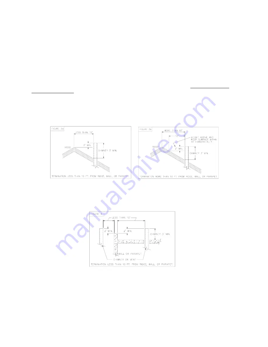
The chimney shall terminate at least 3 feet above the highest point where it passes through the roof of a
building and at least 2 feet higher than any portion of a building within a horizontal distance of 10 feet.
(See Fig. 2a).
Fig. 2: Proper chimney termination height for pitched roofs
If the chimney penetrates a roof more than 10 feet from a ridge, wall or parapet, a minimum of 3 feet
above roof or exit point must be maintained. See Figure 2b.
If the roof is flat rather than the normal residential pitched roof, refer to Figure 3 for proper clearances.
Fig. 3: Proper chimney termination height for flat roofs
4. PROPER VENT CONNECTOR PIPE/CHIMNEY CONNECTION:
The vent connector pipe should extend only to (and not beyond) the inside wall of the chimney (See Fig.
4). A thimble should be used to connect the vent connector pipe to the chimney so that the vent
connector pipe may be readily removed in case of inspection or replacement.
Summary of Contents for OH6FA072D48N
Page 5: ...2...
Page 33: ...30 Heating Speed Set ups 2 Stage OH6FX072DV4 Figure 18 2 ECM 2 stage blower motor speed chart...
Page 64: ...61 VIII Sequence of Operations Flow Chart...
Page 65: ...62...
Page 66: ...63 IX Trouble Shooting Flow Chart...
Page 67: ...64...
Page 68: ...65...
Page 69: ...66...
Page 70: ...67...
Page 72: ...69 Appendix A Replacement Parts Replacement Parts for OH6FA072D...
Page 73: ...70 Replacement Parts for OH8FA119D...
Page 74: ...71 Appendix B Wiring Diagrams OH6FA072D48 PSC Wiring Diagram...
Page 75: ...72 OH6FA072DV4 ECM Wiring Diagram...
Page 76: ...73 OH6FX072DV4 ECM 2 Stage Wiring Diagram...
Page 77: ...74 OH8FA1119D60 PSC Wiring Diagram...
Page 78: ...75 OH8FA1119DV5 ECM Wiring Diagram...
Page 79: ...76...


