All installations and services must be performed by qualified service personnel.
6
When the call for cool is satisfied, the “CC” terminal is de-energized and the cooling off delay of 45 seconds is
started. Forty-five seconds later the blower speed ramps toward zero and the control reverts to Standby Mode.
Dehumidification Operation
If a call for dehumidification is received while the Cool Mode is active, blower speeds will be reduced.
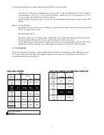
The speed value will be selected from the DEHUM column of the CFM Tables. This input may only be
used on systems using a thermostatic expansion valve (TXV) on the evaporator.
Anti-Short Cycle Operation
To prevent compressor short cycling, a call for cooling will be ignored for four minutes after the
termination of any cooling call. The anti-short cycle delay is also in effect at power-up.
Heat Mode
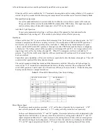
When a call for heat ("W") is received from the thermostat, if the “Cool” mode is not already active, the “T-T”
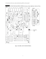
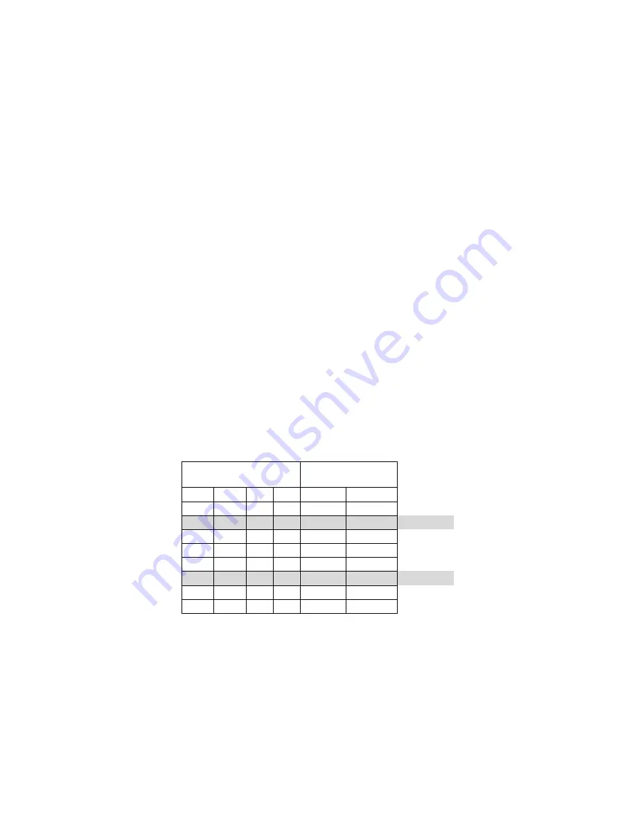
terminal is energized and the blower on delay is started. The on-off pattern of DIP switch SW2 (positions 1
and 2) select one of four blowers on delay values (see Table 1). When the delay time has elapsed, a speed
value is read from DIP switch SW1 positions 1 through 3 (see the CFM Tables) and the blower is ramped up
to that speed. The 2-Stage control will be operated by t-stat through W1 and W2. For 2-stage control with a
single stage t-stat, call for heat will go through W2. When W2 is energized, low fire is activated for 15
minutes. If a call for heat still exists, high fire will be activated and will continue until the demand for heat
has been satisfied.
Counterflow units, in addition, will run at a low blower speed shortly after the burner is brought on. They will
continue at that speed until the delay time has elapsed.
The control remains in steady heat mode until the thermostat is satisfied. When the call for heat signal is
removed, the “T-T” terminal is de-energized and the blower off delay is started. The on-off pattern of DIP
switch SW2 (positions 3 and 4) select one of four blower off delay values (see Table 1). When the delay time
has elapsed, the blower is ramped toward zero.
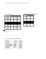
Table 1:
ON and OFF Blower Delay Time Switch Settings
DIP SWITCH 2 SECTION
STATE
BLOWER DELAY
TIMES
2
1
4
3
ON - SEC
OFF - MIN
OFF
OFF
30
OFF
ON
60
Factory Set
ON
OFF
120
ON
ON
240
OFF
OFF
2
OFF
ON
4
Factory Set
ON
OFF
6
ON
ON
8
Motor Blower Speed
Three blower speed outputs are provided. A “G” call for fan will provide the Low speed only. A “W”
heat call will provide the Heat speed only. A “Y” cooling call will provide the Cool speed only.
In the case of thermostat calls for “Y” and “W” together, blower speed selection will be determined by the
input that was first initiated. In the case where the control is in a cooling mode with both “Y” and “W”
inputs energized and then the “Y” input is removed, the cooling blower off time will be executed prior to
the control switching into a heating mode. In the case where the control is in a heating mode with both
“Y” and “W” inputs energized and then the “W” input is removed, the heating blower off time will be
Summary of Contents for OL11-105FDBE
Page 2: ......


