All installations and services must be performed by qualified service personnel.
6
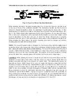
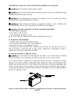
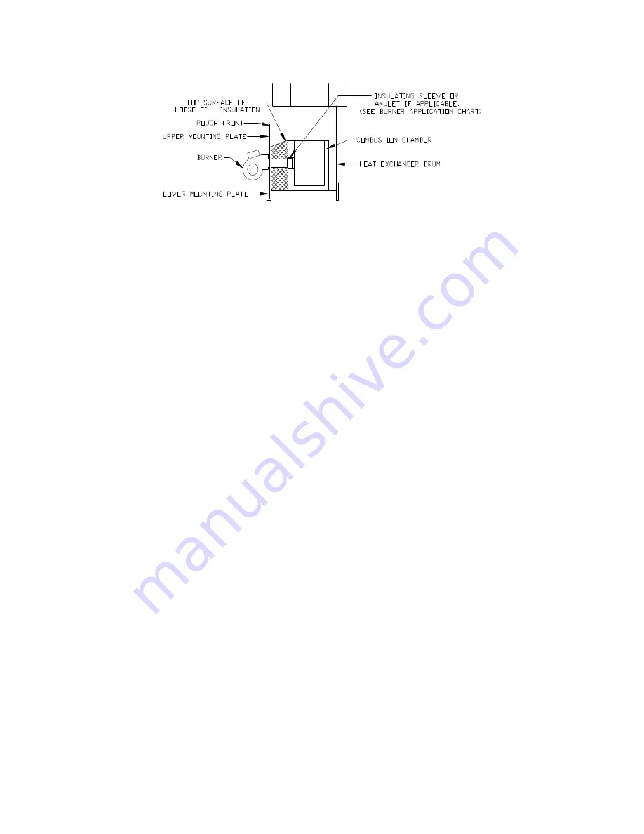
Fig. 5: (Side view) Burner insertion illustration
D. FUEL SYSTEM INSTALLATION
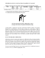
In situations where the oil storage tank is installed at the same level with, or above, the burner, a
single oil supply line run from the oil tank to the burner will be usually be adequate. No return line
will be required. If the oil tank is installed below the burner and the lift exceeds approximately 8-
ft., an oil supply line and an oil return line are recommended. When connecting a return line to the
pump a bypass plug must be installed in the pump, see instruction provided with the burner.
Refer to the Standard for the Installation of Oil-Burning Equipment, NFPA 31-2001, and the oil
burner operating instructions for detailed information on oil storage tank & oil supply/return line
installation.
NOTICE: We recommend installing a high efficiency oil filter, in the oil supply line, capable of
filtering 10 to 20 micron diameter (or preferably smaller) particles from the fuel.
E. WIRING
All wiring must conform to the provisions of local codes or in the absence of these codes with the
provisions of the National Electrical Code, ANSI/NFPA70 (Latest Edition).
The following items are guidelines to complete the wiring portion of the installations.
1. Install the room thermostat according to instructions provided with thermostat. Set the
anticipator to .8 amps.
2. The furnace must be grounded in accordance with local codes and with the National Electrical
Code, ANSI/NFPA70 (Latest Edition).
Summary of Contents for OL20FA151T60 Series
Page 2: ......
Page 5: ...All installations and services must be performed by qualified service personnel iii...
Page 19: ...All installations and services must be performed by qualified service personnel 13...
Page 21: ...All installations and services must be performed by qualified service personnel 15...
Page 23: ...All installations and services must be performed by qualified service personnel 17...


