background image


 20 


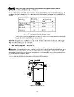
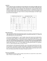
When the oil tank is located below the level of the burner, it is necessary to “lift” the oil to the burner. A 
return line should be connected between the fuel pump and tank. This requires insertion of the "by-pass" 
plug into the fuel pump. If the lift (vertical distance between the supply line inlet and the burner) exceeds 
approximately 12” Hg vacuum, a two-stage pump should be installed with a return line. When a return line 
is used with either single or two-stage pumps, in-line air is automatically returned to the tank, making the 
oil pump and lines self-purging. 
 
Underground tanks should be located outside the building. Installation of above ground tanks is permitted 
inside buildings, under certain conditions, as well as outside. Consult the Standard for Installation of Oil-
Burning  Equipment for  restrictions.  If  permitted,  connect  the  burner  oil  supply  line  near  the  base  of  the 
tank, opposite of the fill end. Connection at this point tends to flush older oil through and out of the tank. 
This  helps  to  prevent the  accumulation  of  rainwater  and  condensed  water  vapor in  the  tank,  which  can 
cause the tank to corrode.  
 
If the oil supplier does not already use oil additives, it is recommended that additives be used to emulsify 
any water accumulation in the oil. 


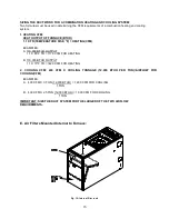
J.  OIL FILTER:


It is strongly recommended that an oil filter assembly be installed in the oil supply line to the unit. This 
filter should have the capacity to trap a 40-50 micron particle. 
 
The filter cartridge should be replaced at least once a year. The filter body should be thoroughly cleaned 
before installing a new cartridge. 
 

K.  ELECTRICAL WIRIING: 


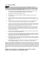
: This appliance must be grounded in accordance with local codes, or in the absence 

of local codes, with the National Electrical Code, ANSI/NFPA 70-1999, or the latest edition. 
 

All wiring must conform to the provisions of local codes or, in the absence of local codes, with the 
provisions of the National Electrical Code, ANSI/NFPA 70-1999, or the latest edition, and this instruction 
manual. 
 
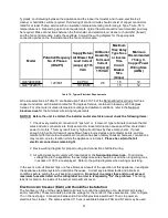
This appliance requires 120 VAC, 60 Hz, single-phase power. Refer to Table 10 for typical electrical 
current draws of the individual appliance motors, recommended sizes for over-current and short circuit 
devices, and minimum recommended field wiring sizes. Electrical service must be brought to the unit from 
a circuit breaker, or fused disconnect switch, in accordance with local codes. The disconnecting switch 
must be located reasonably close to and within sight of the unit. Care must be taken to ensure correct 
polarity when wiring the furnace. 
 
Two-wire service, one “hot” lead (L1) and a common (L2), plus a ground conductor, is required. Connect 
power to the appliance control system at the junction box in the burner compartment. (A knockout fitting is 
provided on the exterior of the burner compartment for this purpose.) A ground wire must be connected to 
the grounding wire in the junction box. 
 
Field wiring of power circuits to the appliance should consist of copper conductors rated for at least        
15 amp service with an insulation temperature rating of at least 75

C temperature rise. Depending upon 

code requirements, rigid or flexible conduit is recommended, and may be required. Connect the electric 
power supply as shown in the wiring diagram located on the inside of the front door. 

Summary of Contents for OL6FA072D48

Page 1: ...ABLE VAPORS AND LIQUIDS IN THE VICINITY OF THIS OR ANY OTHER APPLIANCE c WARNING IMPROPER INSTALLATION ADJUSTMENT ALTERATION SERVICE OR MAINTENANCE CAN CAUSE INJURY OR PROPERTY DAMAGE REFER TO THIS MA...

Page 2: ......

Page 3: ...ATION SECTION 39 A OIL SUPPLY 39 B COMBUSTION AIR SUPPLY 39 C INSPECTION AREAS 39 D STARTING THE BURNER 40 E FILTER CLEANING AND LOCATION 40 IV INSTALLER S INSTRUCTIONS TO USER 41 V DEALER MAINTENANCE...

Page 4: ......

Page 5: ...odel Numbers O L 6 F A 0 7 2 D 4 8 B O L 6 F A 0 7 2 D V 5 B O L 6 F X 0 7 2 D V 5 R O L 6 R A 0 7 2 D 4 8 R O Oil O H Highboy D Downflow L Lowboy L 6 Heat Exchanger Size Identifier 6 F Front F R Rear...

Page 6: ...ED SERVICE PERSON See Page 48 cCAUTION DO NOT ATTEMPT TO MAKE REPAIRS YOURSELF See Page 44 cWARNING The area around the furnace should be kept free and clear of combustible liquids and material especi...

Page 7: ...2...

Page 8: ...mizing oil burner and combustion air blower used to push the products of combustion through the heat exchanger system After installation the furnace and duct system must be adjusted to obtain a temper...

Page 9: ...n air is available to the unit 4 The airflow resistance of the duct system attached to this appliance must fall within the allowable external static pressure range for this unit Refer to the Airflow R...

Page 10: ...e chimney to minimize any horizontal run of flue pipe which may be required 4 A furnace installed in a residential garage must be installed so the burner and ignition source are located higher than 18...

Page 11: ...himney in a worse case situation Condensation most likely will not occur at the bottom of the chimney because the stack gas heats the chimney walls as it rises and the bottom will be heated first This...

Page 12: ...all or parapet a minimum of 3 feet above roof or exit point must be maintained See Figure 2b If the roof is flat rather than the normal residential pitched roof refer to Figure 3 for proper clearances...

Page 13: ...RS AND CONNECTIONS All chimney clean out doors and flue connections must fit tightly so they will seal to avoid air leaks 7 NO INTERCONNECTED CHIMNEY FLUES If chimney flues are divided or there are mu...

Page 14: ...fiber or mineral wool batts 12 9 6 5 4 3 c 0 024 24 gauge sheet metal over 1 glass fiber or mineral wool batts reinforced with wire on rear face with ventilated air space 9 6 5 3 3 3 d 3 1 2 thick ma...

Page 15: ...ires that the flue exit out the left side casing remove screw securing the 90 deg elbow and rotate it 90 Then remove knock out in side casing and extend vent through the opening A trim collar may be o...

Page 16: ...s before the draft regulator Note Draft over fire may be positive for high fire applications but not to exceed 02 WC D DUCT WORK AIR CONDITIONING If the furnace is used in connection with summer air c...

Page 17: ...ton of air conditioning For reference a ton of A C 12 000 BTU hr removed from the space Refer to Examples 1 2 page 15 for a sample calculation of how to determine the required minimum airflow rate 5...

Page 18: ...of the take off and the outlet register or return grill should then be summed together to determine the total pressure drop for each branch This value should be close to the assumed value for the pre...

Page 19: ...r heat gain to the ducts 8 As a final step in the installation the appliance must be adjusted to deliver a temperature rise within the range of 50 to 80 F Adjust the blower motor speed to obtain a tem...

Page 20: ...10 000 BTUH OUTPUT 1 1 X 85 F TR 1176 CFM FOR HEATING B 110 000 BTUH OUTPUT 1 1 X 70 F TR 1429 CFM FOR HEATING 2 COOLING CFM 400 CFM X COOLING TONNAGE 12 000 BTUH PER TON AIRFLOW FOR COOLING CFM EXAMP...

Page 21: ...Area in square inches The Thermo Products supplied filter can be cut to size to fit other filter retention systems as long as the maximum air velocity is not exceeded NOTICE Any internal stiffeners us...

Page 22: ...remove this retainer when installing burner Fig 12 Typical location of the over fire air tap and components in burner mounting plate area Fig 13 Burner insertion illustration Top view When mounting th...

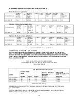
Page 23: ...6 Beckett Carlin Riello burners specifications INSULATOR S SLEEVE OR N NONE THE NOZZLE SIZE GIVES THE NOMINAL FLOWRATE IN GPH FOLLOWED BY THE SPRAY ANGLE IN DEGREE S AND THE SPRAY PATTERN EITHER H FOR...

Page 24: ...pplied to the male member of a joint The first two threads on the end of the male member of each pipe joint should be clean and free from thread sealant 8 Connection of the oil supply piping to the ap...

Page 25: ...thoroughly cleaned before installing a new cartridge K ELECTRICAL WIRIING This appliance must be grounded in accordance with local codes or in the absence of local codes with the National Electrical C...

Page 26: ...s to ensure that all wires and wire connectors are firmly secured A loose terminal can cause poor flow of electrical power to motors This may result in very high current draws by these components If g...

Page 27: ...ting and or cooling cycle Calibration will help to produce a more constant indoor temperature by adjusting the length of the heating cooling cycle to fit the application A vital consideration of this...

Page 28: ...the needle on to the measurement scale of the instrument proceed as follows 1 Wrap 10 loops of single strand insulated thermostat wire around the prongs of an ammeter refer to Figure 17 Set the scale...

Page 29: ...ting mode for proper operation If a digital ammeter is used read the current draw directly from meter Steps 1 through 3 are not required The meter reading is the correct anticipator setting L Blower M...

Page 30: ...FF 2 OFF 1 OFF 755 73 o 1 1 93 1 7 154 3 OFF 2 OFF 1 ON 826 66 o 80 o 1 2 105 1 9 168 3 OFF 2 ON 1 OFF 898 61 o 74 o 1 8 180 2 3 219 Factory SW1 Switch Settings 3 OFF 2 ON 1 ON 983 56 o 67 o 84 o 2 0...

Page 31: ...chart Fan Control SW 1 Switch Setting Clg Tonnage Cool Continuous 0 2 0 5 6 OFF 5 OFF 4 OFF 2 799 500 1 2 100 1 9 162 6 OFF 5 OFF 4 ON 2 5 1017 508 1 8 155 2 5 223 6 OFF 5 ON 4 OFF 3 1210 605 2 5 223...

Page 32: ...l Static pressure in WC Low 4 1 408 4 0 398 4 0 395 3 9 385 3 8 378 ML 5 3 540 5 3 535 5 2 527 5 1 512 4 9 500 MED 6 6 665 6 4 644 6 2 634 5 9 609 5 6 584 MH 7 6 772 7 2 739 6 9 713 6 6 682 6 4 663 Hi...

Page 33: ...Wiring to Burner Harness Wires Beckett Connections Riello Connections Thermostat Humidistat connections C Common ground W Thermostat call for heat R 24 VAC to thermostat G Thermostat call for fan Y Th...

Page 34: ...will light when the control receives a call for dehumidification Refer to the Cool Mode section for the control operation Thermostat call for fan G 24 VAC thermostat input A call for fan is recognized...

Page 35: ...the control will operate the fan relay K4 and power the Low blower speed terminal The fan mode will be operated as long as the G input is calling and neither the Heat mode nor the Cool mode is callin...

Page 36: ...d tap only In the case of thermostat calls for Y and W together blower speed selection will be determined by the input that was first initiated In the case where the control is in a cooling mode with...

Page 37: ...dicate the presence of these signals The red Board Status LED has two functions It will light when the board recognizes a valid input signal and will stay lit until all valid signals are removed This...

Page 38: ...d relatively clean of dirt and debris e Make sure the thermostat is set in the heating mode of operation Operating Instructions i STOP Read the safety information above ii Set the thermostat to the lo...

Page 39: ...ollowing test instruments are required A smoke density measuring and rating device A carbon dioxide CO2 or oxygen O2 analyzer A flue gas temperature measuring device e g thermocouple or thermister pro...

Page 40: ...e the air band or shutter on the burner until a trace smoke reading is measured NOTICE To achieve proper combustion and the efficiencies listed in sales brochures instruments must be used to secure CO...

Page 41: ...r n Start and stop the unit several times while checking for proper ignition of the burner The flame should ignite and stabilize without any significant rumbles or pulsations 3 Adjustment Of Heat Inpu...

Page 42: ...e heat exchanger surfaces will reduce temperature rise In general a lower temperature rise through the heating section will result in higher heating efficiency Temperature rise supply air temperature...

Page 43: ...limit control should act to shutdown the burner vi Shut off the electrical power IMPORTANT Remove blockage or reconnect blower motor and restore power c Make certain the thermostat will automatically...

Page 44: ...erials damage from rust or corrosion soot or carbon build up EXTERIOR OF FURNACE The furnace exterior should be inspected for signs of excessive heat such as discoloration of materials and damage from...

Page 45: ...ments Contact a qualified service person to adjust and start burner E FILTER CLEANING AND LOCATION cWARNING To avoid injury from moving parts hot surfaces or electrical shock shut off the power to the...

Page 46: ...n and Routine Maintenance section of this manual 5 That failure to maintain and operate this appliance in accordance with these instructions could result in hazardous conditions property damage and bo...

Page 47: ...2 Burner Visually check the burner and below the burner for indications of oil leaks Correct any if found Remove the burner and measure the ignition electrode gap It should be set to 5 32 inch Adjust...

Page 48: ...rner and the burner mounting plates When removing the clean out plugs turn T handle counterclockwise approximately two 2 full turns or just until the plug is able to be pulled from tube Take care not...

Page 49: ...44 Figure 24 Heat Exchanger Clean Outs Vacuum Hose Length OL6 8FT Fig 25 Recommended method and device for cleaning inside of heat exchanger...

Page 50: ...bly to assure they are not exceeding rating label current specifications for each component Also refer to Table 10 in the electrical wiring section of this manual for electrical specifications on thes...

Page 51: ...mum operating efficiency G EXTENDED APPLIANCE SHUTDOWN Should the appliance be shutdown or turned off for an extended period of time several steps can be taken to help insure a smooth and reliable res...

Page 52: ...upply line 6 Open the inspection cover on the upper mounting plate 7 Turn on the electrical power to start the burner If the burner does not start immediately reset the manual overload switch on the m...

Page 53: ...ng it Do not attempt to make repairs yourself Contact your local qualified heating contractor Under normal conditions this appliance will operate in either heating or cooling mode depending upon the m...

Page 54: ...mbling the unit Never operate the appliance without clean air filters in place This appliance requires air for combustion ventilation and cooling Do not block or obstruct air openings in the unit and...

Page 55: ...r junction box on top of the burner blower and remove the plug in portion of the cad cell by pulling it forward from and clear of the receptacle Connect an ohmmeter across cad cell pins With the cell...

Page 56: ...51 VIII Sequence of Operations Flow Chart...

Page 57: ...52...

Page 58: ...53 IX Trouble Shooting Flow Chart...

Page 59: ...54...

Page 60: ...55...

Page 61: ...56...

Page 62: ...57...

Page 63: ...LINER FUEL LINE FILTER DRAFT CONTROL COMBUSTION TESTS Operate burner at least 10 minutes before CO2 in stack pipe INITIAL SERVICE SERVICE SERVICE INSTALLATION Draft Over fire Draft in stack pipe Smok...

Reviews: