background image

3

Warning

This manual must be carefully read and thor-

oughly understood before operating the unit, fail-

ure to follow directions or precautionary meas-

ures could result in serious adverse effects.

This equipment must be used only as specified

in these instructions. If used in a manner other

than as specified, the protection provided by the

equipment may be impaired.

This equipment is intended for indoor use only.

This equipment must be earth grounded for safe

operation.

Maximum ratings of accessories that may be

plugged into convenience outlet: Load current 2

Amps. @ 115VAC, Leakage Current 250 micro

Amps.

Caution

The aluminum evaporator and other portions of these

units should not be exposed to the corrosive effects of

acidic or caustic materials. Extreme care must be exer-

cised if such materials are stored within to prevent voiding

the warranty. This Incubator is NOT suitable for flamma-

ble material storage.

Important

When operating at 100% cooling, the compressor runs

continuously and thus cools continuously. If no manual

defrosting is conducted for over 2 weeks, ice will build

and the unit will not maintain temperature. See

Defrosting.

Safety Information

Warning

Warnings alert you to a possibility of

personal injury.

Caution

Cautions alert you to a possibility of

damage to the equipment.

Note

Notes alert you to pertinent facts and

conditions.

Hot Surface

Hot surfaces alert you to a possibility

of personal injury if you come in con-

tact with a surface during use or for a

period of time after use.

Alert Signals

Caution

Risk of electric shock.

Summary of Contents for 3554-35A

Page 1: ...Low Temperature Incubator Owner Operator Manual and Parts List Model No 3554 35A 115 VAC LT1883X4 4 2 09 Serial Number ______________________________ ...

Page 2: ...plays 8 Controls 8 Display and Indicators 8 Operation 9 General Function Checks 9 Controller Operation 9 Changing Chamber Temperature Control Setpoint 10 Accessing Controller Menus 11 Safety Thermostat 12 Maintenance 13 Cleaning 13 Defrosting 13 Calibration 14 Repair 15 Replacing Temperature Controller Alarm or S2 15 Replacing RTD Temperature Sensor 15 Replacing SSR1 K1 K2 or T1 16 Replacing FAN S...

Page 3: ...ld not be exposed to the corrosive effects of acidic or caustic materials Extreme care must be exer cised if such materials are stored within to prevent voiding the warranty This Incubator is NOT suitable for flamma ble material storage Important When operating at 100 cooling the compressor runs continuously and thus cools continuously If no manual defrosting is conducted for over 2 weeks ice will...

Page 4: ...p to 300 stan dard BOD bottles or similar containers The 5 reinforced shelves can handle up to 60 lbs of sample weight each Features include 5 Removable shelves 6 Molded door shelves Door Lock with key Microprocessor based temperature controller with temperature readout to 1 C 3 Cooling control modes High precision with cooling high precision without cooling and Frost free with variable cooling So...

Page 5: ... BOD bottles Shipping Weight 283 lb 128 kg Operating Environment Temperature Range 10 C to 40 C Humidity Range 0 to 90 RH Maximum Altitude 6600 ft 2 km Air clearances Back top and sides 3 0 min Over voltage Category II IEC664 Pollution Degree 2 IEC664 Performance Characteristics Operating Range 10 to 60 C Uniformity 0 5 C Stability 0 2 C Display Readability 0 1 C Per ASTM method E 1292 94 cooling ...

Page 6: ...ation could cause degrading of mechanical or electrical com ponents 1 Unbolt and remove the wooden slats under neath unit 2 Remove all protective tape from doors and shelves 3 Clean interior and exterior with warm soap and water Shipping tape residue can be removed using isopropyl alcohol 4 Uncoil line cord from rear of unit Connect the plug to a power outlet that complies with the electrical requ...

Page 7: ... the unit Use the screws included with the unit and the pre drilled holes located near the top corners Do not drill additional holes which could result in damage to the unit 2 Move the unit into position and attach the brack ets to a structurally sound wall or other support The brackets will ensure that the appropriate 3 inches of clearance from the wall is maintained 7 INSTALLATION Mount brackets...

Page 8: ...s DISPLAY On front panel Displays chamber and set point temperatures in C and prompts from menu INDICATORS On front panel DELAY Lights when delay start timer for compressor is timing Will begin timing when power is first applied or when cooling compressor is turned off ALARM Indicates that chamber temperature is not within limits and the safety relay is opened COOL Lit when cooling compressor is o...

Page 9: ...turn to normal control mode Press SET to display control setpoint display should read 25 0 If the control setpoint or any of the other parameters aren t set correctly use the L or M keys while pressing SET to change the setting 4 The DELAY LED will be lit for 7 minutes after power is first applied the COOL LED will be out during this delay period When the DELAY LED goes out the COOL LED will light...

Page 10: ...our for unit to stabilize at the new setpoint temperature After the incubator temperature has stabilized place sam ples into incubator chamber For best results arrange samples evenly throughout the chamber Liquid samples should be covered to prevent evaporation and eventual frost build up on evaporator coils particularly when oper ating below ambient The Low Temperature Incubator has an internal 2...

Page 11: ...arm is activated and if the control setpoint can be changed Range 0 0 to 0 2 0 0 Mode Normal mode that allows the user to change setpoint Alarm activates if chamber temperature cham ber and setpoint temperature setpoint are as follows Chamber 15 0 C and chamber setpoint 3 or Chamber 40 0 C and chamber setpoint 3 While ALARM is activated the safety relay is opened interrupting power to the heater f...

Page 12: ... the chamber temperature reaches the setpoint and is stable protection mode 0 2 can be set Safety Thermostat As an added safety feature the incubator has a thermo stat in the heater compartment that limits the upper cham ber temperature to 65 C in the event that all other con trols fail OPERATION Note If the chamber temperature falls out side the setpoint by 3 C the ALARM will activate and safety ...

Page 13: ... chamber during this procedure 1 Refer to Accessing Controller Menus Press and hold MENU key until CAL is displayed then release and press MENU again until Pct is dis played 2 Select 50 in the Pct menu then press MENU key twice to return control mode 3 Allow incubator to remain in this mode for about 24 hours or until frost disappears 4 Use the MENU key to re establish the previous selection for P...

Page 14: ...etric center of the chamber 2 Set the controller to the desired operating tem perature in 100 cooling mode and allow 2 hours stabilization 3 Note the chamber temperature on the controller display and the temperature at the geometric center 4 Subtract the chamber display reading from the geometric center reading 5 Enter into the Calibration Mode as described in Accessing Menu 6 Press and hold SET k...

Page 15: ... Set DS1 2 B to off up 6 Attach wires previously removed from old con troller to new controller 7 Mount new controller and bezel then apply power 8 Refer to Calibration section of this manual to calibrate new controller Replacing RTD Temp Sensor 1 Disconnect incubator from power source 2 Refer to Replacing Temp Controller but only remove sensor wires from TB2 3 Open incubator door and remove screw...

Page 16: ...erating Replacing FAN S1 or THM1 1 Disconnect incubator from power source 2 Remove basket and shelves from chamber area 3 Remove screws from heater cover at rear of chamber 4 Rotate heater cover to right side of chamber 5 Fan is located on back wall and S1 and THM1 are on switch panel attached to heater cover 6 Replace desired part then coat electrical con nections with RTV102 or other electrical ...

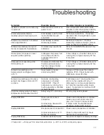
Page 17: ...ine Test line voltage of outlet is required while operating Temperature readings go far Open heater or heater Unplug unit from power then refer to below setpoint and trigger alarm control relay SSR1 replacing HTR1 Check heater with at 15 C OHM meter about 29 ohms Temperature readings go far above Defective cooling relay If compressor isnʼt running while Cool setpoint and triggers alarm at 40 C com...

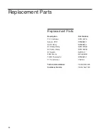
Page 18: ...02214 Sensor RTD SPN88613 SSR1 Relay SPN88616 K1 Safety Relay SPN102260 K2 Comp Relay SPN102259 S1 Switch SWX143 FAN1 Motor RF1639X33 THM1 Thermostat SPN88612 T1 Transformer TNX135 Technical Assistance 1 800 926 0505 Customer Service 1 800 766 7000 Replacement Parts ...

Page 19: ...19 Wiring Diagram ...

Page 20: ...c dealer from whom you purchased this unit or can be obtained promptly from the factory When service or replacement parts are needed we ask that you check first with your dealer If the dealer cannot handle your request then contact our Customer Service Department at 563 556 2241 or 800 553 0039 Prior to returning any materials please contact our Customer Service Department for a Return Materials A...

Page 21: ...21 ...

Page 22: ...22 ...

Page 23: ...23 ...

Page 24: ... misuse including use inconsistent with written operating instructions for the product mishandling contamination overheating modification or alteration of the product by any customer or third party or iii use of replacement parts that are obtained from a party who is not an authorized dealer of Thermo Scientific prod ucts Heating elements because of their susceptibility to overheating and contamin...

Reviews: