background image

8600 Series

10-11

Thermo Scientific

Section 10

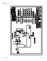
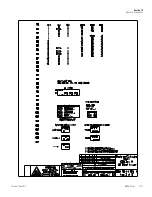
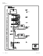
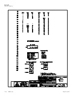
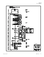
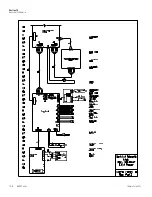
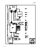
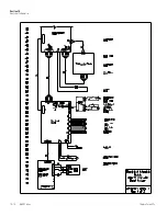
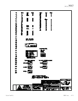
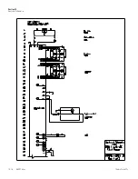
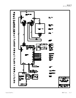
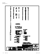
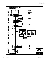
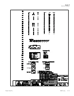
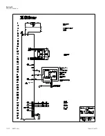
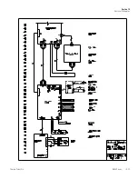
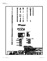
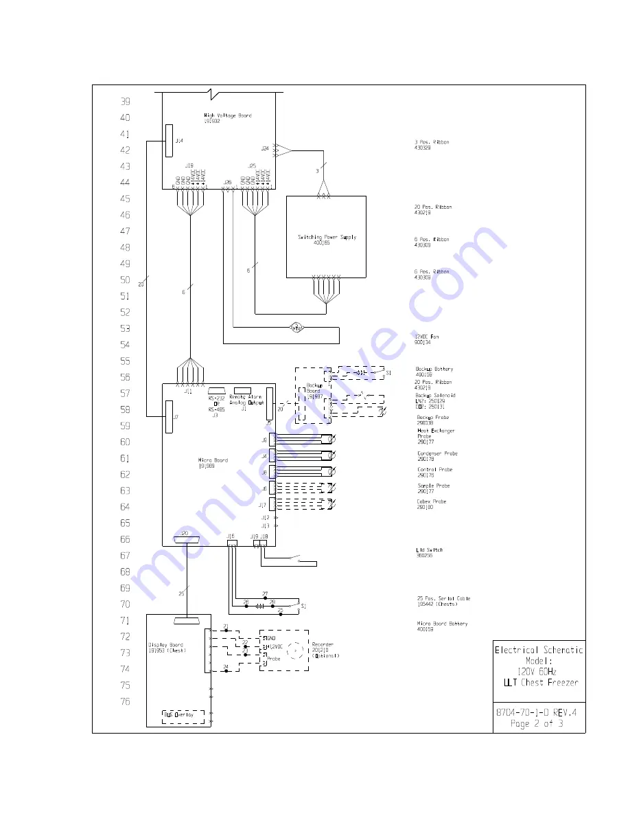
Electrical Schematics

Summary of Contents for Forma 8600 Series

Page 1: ...sit us online to register your warranty www thermoscientific com labwarranty User Manual Thermo Scientific Forma 8600 Series 40C and 86C ULT Chest Freezer Operating and Maintenance Manual 7028700 Rev...

Page 2: ...Description Qty 213F Key 2 380520 Neoprene Cap 2 510016 1 4 20 x 5 1 2 Bolt 2 195763 Retaining Clip 1 370563 Remote Alarm Connector 1 Packing List 40C Models Covered Number Cu ft Voltage Hz 703CA 3 1...

Page 3: ...any damages direct or incidental arising out of or related to the use of this manual The 40C and 86C freezers see page i for model numbers described in this manual are high performance units which ca...

Page 4: ...Extreme temperature hazards hot or cold Use special handling equipment or wear special protective clothing WEEE Compliance Thermo Fisher Scientific has contracted with companies for recycling disposa...

Page 5: ...or replacement parts or provide you with on site service We can also provide you with a quotation on our Extended Warranty for your Thermo Scientific products Whatever Thermo Scientific products you n...

Page 6: ...Cord 1 10 Freezer Start Up 1 11 Set Operating Temperature 1 11 Set Low Temperature Alarm 1 12 Set High Temperature Alarm 1 12 Access Code 1 13 Run Mode 1 13 Calibrate 2 1 Calibrate Mode 2 1 Calibrate...

Page 7: ...ly 6 1 Install Temperature Probe 6 2 BUS Control Panel 6 4 Connect Probe Solenoid Harness 6 4 Set Optional BUS Set Point 6 5 Configure Optional Back Up System BUS 6 5 Test the BUS 6 6 Disconnect Fitti...

Page 8: ...ypad displays and indicators BUS Optional Back Up System panel Optional temperature recorder 7 day one pen or datalogger Keylock keyed lid lock Optional Back Up System Controls Control Panel Optional...

Page 9: ...olenoid RS 232 or RS 485 interface Power Switch mains disconnect Optional BUS battery just behind this panel Optional BUS Connections RS 232 or RS 485 Interface Remote Alarm Contacts and Analog Output...

Page 10: ...eezer filter location Battery power switch freezer and BUS Thermocouple receptacle Battery mounting bracket Freezer and optional BUS battery Figure 1 5 Probe Cover aaaaaaa aaaaaaa aaaaaaa aaaaaaa aaaa...

Page 11: ...probe access port Figure 1 7 Freezer Left Side Sidecar panel removed O aaaaaaaa aaaaaaaa aaaaaaaa aaaaaaaa aaaaaaaa aaaaaaaa aaaaaaaa aaaaaaaa aaaaaaaa aaaaaaaa aaaaaaaa aaaaaaaa aaaaaaaa aaaaaaaa aa...

Page 12: ...y Hot Condenser indicates a hot condenser condition Message Center displays system status and alarms Scroll for Parameters Arrows moves through the choices of the selected mode Up and Down Arrows Incr...

Page 13: ...each of the modes 1 6 8600 Series Thermo Scientific Section 1 Installation and Start up Table 1 1 Modes of Operation Panel Keys Display Indicators cont Run Settings Calibrate Configuration Default Mod...

Page 14: ...center displays the system status Mode at all times The message SYSTEM OK displays during normal operation Alarm messages are displayed if the system detects an alarm condition See Section 4 Alarms T...

Page 15: ...ons of the pre tapped holes 8600 Series freezers have a data communications interface The factory default setting is RS 232 The wiring identification for the interface is shown in Figure 1 10 One nine...

Page 16: ...The RS 232 is not compatible with 1535 Monitor Alarm System s 86C units only 8600 Series freezers have remote alarm contacts and analog output See Figures 1 3 and 1 4 for the location of the remote al...

Page 17: ...n it to Standby mode During initial freezer start up the system battery may require charging and the Low Battery message may appear in the message center Note Ensure the battery switch is turned to St...

Page 18: ...th a temperature set point of 80 C 86C units or 40 40C units To change the operating temperature set point 1 Press the Mode key until the Settings indicator lights 2 Press the right arrow until SET PT...

Page 19: ...the high temperature alarm is disabled until the cabinet reaches set point or 12 hours elapse s The low temperature alarm activates an audible visual warning when the freezer chamber temp reaches or...

Page 20: ...e freezer The run mode displays the cabinet temperature on the temperature display and SYSTEM OK on the message center under normal operating conditions In addition the Run mode allows display of the...

Page 21: ...Parameters Press to return to previous parameter Press to return to previous parameter Press to return to previous parameter Low Alarm Set Point High Alarm Set Point Control Set Point To Set Settings...

Page 22: ...of the measuring device See Chart 2 1 at the end of this section for more detail 1 Press the Mode key until the Calibrate indicator lights 2 Press the right arrow until CONT T XX X appears in the mes...

Page 23: ...o CONFIGURATION mode Numbers decrease Press Enter to save setting Scroll for Parameters Mode SAMPT XX X Scroll for Parameters Press to return to previous parameter Press to return to previous paramete...

Page 24: ...nitiate the test The temperature on the display will begin to increase until the high alarm set point has been reached The audible alarm will sound and the alarm indicator will flash Press the Silence...

Page 25: ...or will go off The Low Battery light will stay on until a future battery test is performed and passed To test the charge of the BUS battery 1 Press the Mode key until the Configuration indicator light...

Page 26: ...he Mode key until the Configuration indicator lights 2 Press the right arrow until CLR HS ALARM is displayed in the message center 3 Press Enter to clear the alarm To set the Access Code 1 Press the M...

Page 27: ...al back up system BUS allows the user to select which type of gas is injected into the freezer chamber The options are CO2 and LN2 1 Press the Mode key until the Configuration indicator lights 2 Press...

Page 28: ...Scroll for Parameters Press to return to previous parameter Press to return to previous parameter Press to return to previous parameter LowAlarm Test HighAlarm Test System Battery Test To Configure M...

Page 29: ...PCONTROL CONTROLprobe Press Enter to save the setting Mode Scroll for Parameters Press to return to previous parameter Display Temperature SAMPLE probe Mode Scroll for Parameters Mode Press Enter to s...

Page 30: ...vious page Configuration Mode Chart 3 1 Page 3 of 3 Warm Excursion To Configure COLD EX XX Mode Scroll for Parameters Press to return to previous parameter Cold Excursion Mode Scroll for Parameters Mo...

Page 31: ...h Temperature Alarm TEMP IS HIGH 1 min 15 min Yes Low Temperature Alarm TEMP IS LOW 1 min 15 min Yes Door Ajar DOOR IS OPEN 1 min 15 min No Low Battery LOW BATTERY 1 min 8 hours No Low BUS Battery opt...

Page 32: ...in the message center one at a time updating at 5 second intervals Pressing Silence during multiple alarms causes all active alarms to be silenced and to ring back in 15 minutes An internal communicat...

Page 33: ...ange 55 Hz Freq 70 Hz for 60 Hz units 40 Hz Freq 55 Hz for 50 Hz units Response This condition is checked at power on reset and if it is active the unit will NOT power up The unit will indefinitely di...

Page 34: ...s failed to pass its CRC CCITT checksum integrity test Response The display performs this check at startup and the display board will fail to startup with out any error indication if it does not pass...

Page 35: ...nse The display shows Er11 N A SMPL PRB FLT Name Sample Probe Sensor Failure Description This condition indicates that the sample probe sensor has failed to produce a valid reading for 12 consecutive...

Page 36: ...ove 3 Wash the filter material using water and a mild detergent 4 Dry by pressing between two towels 5 Install the filter back into the grille and close the door Depending upon environmental condition...

Page 37: ...g a soft cloth remove any frost build up from the gasket sub lids and lids The clean gasket alarm occurs every three months as a reminder to remove frost build up from the gasket and doors Press the S...

Page 38: ...Replace the recorder bezel 8 Turn the battery power switch to Standby mode 9 Close lower panel door Note For a consistent and dependable charge replace the battery every 2 years Replacement batteries...

Page 39: ...reads less than 10 8 volts replace the battery If above 10 8 re install as previously 9 Re install side panel Turn the battery power switch to Standby mode then close lower door Turn power switch On...

Page 40: ...eviously described This prepares the unit for storage Turn Off the battery power switch O Turn Off the freezer power switch Note If the unit has been in service turn it off and disconnect the power co...

Page 41: ...to recover to set point between shelves Fill a chest by starting at the left side near the probe Filling with room temperature racks will result in a long pull down time Fill unit with frozen product...

Page 42: ...into the chamber to keep the chamber temperature within the specified range The BUS operates on an internal 12 volt rechargeable battery which is kept charged during normal operation by the integral b...

Page 43: ...O2 supply cylinder it must be equipped with a siphon tube s 1 Plug the solenoid probe connector into the BUS connection Loop the probe wire back into the base side car Secure the connector with a scre...

Page 44: ...s securing the probe cover see Figure 6 5 5 Route the BUS probe through the probe port approximately 12 Secure the back up probe to the temperature probe using a small tie wrap Figure 6 5 6 Seal aroun...

Page 45: ...h batteries The following section describes the configuration and operation of the BUS Warning When activated this unit injects liquid nitrogen or carbon dioxide Liquid nitrogen can cause serious free...

Page 46: ...optional BUS can be configured for LN2 or CO2 supply Section 3 Configuration contains instructions for setting the BUS type The optional back up system is designed to inject CO2 or LN2 into the freeze...

Page 47: ...up verify the BUS injects at the desired temperature Displayed temperature may vary by a few degrees from inject temperature due to the differences in probe locations 3 Recommended Maintenance Monthl...

Page 48: ...to flash Count the number of flashes to determine the present program setting 4 To change the program setting press the left or right arrows to increase or decrease the count 5 When the desired progra...

Page 49: ...egins to move Release the button when the pen position matches the thermometer Note The felt tip pen on the recorder requires periodic replacement Usually the ink will appear to fade before replacemen...

Page 50: ...irements 15 Amp Dedicated Circuit 15 Amp Time Delay Breaker 15 Amp Dedicated Circuit 15 Amp Time Delay Breaker 20 Amp Dedicated Circuit 20 Amp Time Delay Breaker Shipping Weight 716 lbs 325 kg Number...

Page 51: ...Amp Dedicated Circuit 15 Amp Time Delay Breaker 15 Amp Dedicated Circuit 15 Amp Time Delay Breaker Shipping Weight 821 lbs 372 kg Number Model 820CV 8708 820CD 8709 820CA 8710 Temperature Range 50 C 5...

Page 52: ...rements 15 Amp Dedicated Circuit 15 Amp Time Delay Breaker 15 Amp Dedicated Circuit 15 Amp Time Delay Breaker 20 Amp Dedicated Circuit 20 Amp Time Delay Breaker Shipping Weight 716 lbs 325 kg Number M...

Page 53: ...Amp Dedicated Circuit 15 Amp Time Delay Breaker 15 Amp Dedicated Circuit 15 Amp Time Delay Breaker Shipping Weight 764 lbs 347 kg Number Model 720CV 8734 720CD 8736 720CA 8737 Temperature Range 10 C 1...

Page 54: ...ay For ULT models rated 230V 50Hz intended for import into the EU the following sizes are designed for use with the following amounts of fluorinated greenhouse gases __________________________________...

Page 55: ...8600 Series 8 1 Thermo Scientific Section 8 Spare Parts...

Page 56: ...8 2 8600 Series Thermo Scientific Section 8 Spare Parts Exploded Drawing 3 cu ft Chest Freezer Heat Exchanger 8700 201 1 B Rev 0 Page 1 of 1...

Page 57: ...8600 Series 8 3 Thermo Scientific Section 8 Spare Parts Exploded Drawing Model 3 cu ft Chest Freezer Lid 8700 200 1 B Rev 1 Page 1 of 2 F TS...

Page 58: ...8 4 8600 Series Thermo Scientific Section 8 Spare Parts Exploded Drawing Model 3 cu ft Chest Freezer Lid 8700 200 1 B Rev 1 Page 2 of 2 F TS...

Page 59: ...8600 Series 8 5 Thermo Scientific Section 8 Spare Parts Exploded Drawing 3 6 7 cu ft Chest Freezer Cabinet Assy F TS 8700 200 2 B Rev 0 Page 1 of 2...

Page 60: ...8 6 8600 Series Thermo Scientific Section 8 Spare Parts Exploded Drawing 3 6 7 cu ft Chest Freezer Cabinet Assy F TS 8700 200 2 B Rev 0 Page 2 of 2...

Page 61: ...8600 Series 8 7 Thermo Scientific Section 8 Spare Parts 8700 200 3 B Rev 2 Page 1 of 2 3 0 cu ft Chest Freezer Base F TS...

Page 62: ...8 8 8600 Series Thermo Scientific Section 8 Spare Parts 8700 200 3 B Rev 2 Page 2 of 2 3 0 cu ft Chest Freezer Base F TS...

Page 63: ...8600 Series 8 9 Thermo Scientific Section 8 Spare Parts Exploded Drawing Model 12 7 17 and 20 cu ft Chest Freezer Lid 8704 200 1 B Rev 1 Page 1 of 2...

Page 64: ...8 10 8600 Series Thermo Scientific Section 8 Spare Parts Exploded Drawing Model 12 7 17 and 20 cu ft Chest Freezer Lid 8704 200 1 B Rev 1 Page 2 of 2...

Page 65: ...8600 Series 8 11 Thermo Scientific Section 8 Spare Parts Exploded Drawing 12 7 cu ft Chest Freezer Cabinet F TS 8704 200 2 B Rev 0 Page 1 of 2...

Page 66: ...8 12 8600 Series Thermo Scientific Section 8 Spare Parts Exploded Drawing 12 7 cu ft Chest Freezer Cabinet F TS 8704 200 2 B Rev 0 Page 2 of 2...

Page 67: ...8600 Series 8 13 Thermo Scientific Section 8 Spare Parts 8704 200 3 Rev 4 Page 1 of 2 12 7 cu ft Chest Freezer Side Car F TS...

Page 68: ...8 14 8600 Series Thermo Scientific Section 8 Spare Parts 8704 200 3 Rev 4 Page 2 of 2 12 7 cu ft Chest Freezer Side Car F TS...

Page 69: ...8600 Series 8 15 Thermo Scientific Section 8 Spare Parts 902 204 1 B Rev 2 Page 1 of 2 230V RELAY ENCLOSURE ASSEMBLY...

Page 70: ...902 204 1 B Rev 2 Page 2 of 2 230V RELAY ENCLOSURE ASSEMBLY 8 16 8600 Series Thermo Scientific Section 8 Spare Parts...

Page 71: ...8600 Series 8 17 Thermo Scientific Section 8 Spare Parts Exploded Drawing 120V Relay Enclosure Freezers 902 204 2 B Rev 1 Page 1 of 2...

Page 72: ...Exploded Drawing 120V Relay Enclosure Freezers 902 204 2 B Rev 1 Page 2 of 2 8 18 8600 Series Thermo Scientific Section 8 Spare Parts...

Page 73: ...8600 Series 8 19 Thermo Scientific Section 8 Spare Parts 120230 01 1 B Rev 7 Page 1 of 2 Chest Freezer Start Component Enclosure Assembly...

Page 74: ...8 20 8600 Series Thermo Scientific Section 8 Spare Parts 120230 01 1 B Rev 7 Page 2 of 2 Chest Freezer Start Component Enclosure Assembly...

Page 75: ...8600 Series 9 1 Thermo Scientific Section 9 Refrigeration Schematics...

Page 76: ...9 2 8600 Series Thermo Scientific Section 9 Refrigeration Schematics...

Page 77: ...8600 Series 9 3 Thermo Scientific Section 9 Refrigeration Schematics...

Page 78: ...9 4 8600 Series Thermo Scientific Section 9 Refrigeration Schematics...

Page 79: ...8600 Series 9 5 Thermo Scientific Section 9 Refrigeration Schematics...

Page 80: ...9 6 8600 Series Thermo Scientific Section 9 Refrigeration Schematics...

Page 81: ...8600 Series 10 1 Thermo Scientific Section 10 Electrical Schematics...

Page 82: ...10 2 8600 Series Thermo Scientific Section 10 Electrical Schematics...

Page 83: ...8600 Series 10 3 Thermo Scientific Section 10 Electrical Schematics...

Page 84: ...10 4 8600 Series Thermo Scientific Section 10 Electrical Schematics...

Page 85: ...8600 Series 10 5 Thermo Scientific Section 10 Electrical Schematics...

Page 86: ...10 6 8600 Series Thermo Scientific Section 10 Electrical Schematics...

Page 87: ...8600 Series 10 7 Thermo Scientific Section 10 Electrical Schematics...

Page 88: ...10 8 8600 Series Thermo Scientific Section 10 Electrical Schematics...

Page 89: ...8600 Series 10 9 Thermo Scientific Section 10 Electrical Schematics...

Page 90: ...10 10 8600 Series Thermo Scientific Section 10 Electrical Schematics...

Page 91: ...8600 Series 10 11 Thermo Scientific Section 10 Electrical Schematics...

Page 92: ...10 12 8600 Series Thermo Scientific Section 10 Electrical Schematics...

Page 93: ...8600 Series 10 13 Thermo Scientific Section 10 Electrical Schematics...

Page 94: ...10 14 8600 Series Thermo Scientific Section 10 Electrical Schematics...

Page 95: ...8600 Series 10 15 Thermo Scientific Section 10 Electrical Schematics...

Page 96: ...10 16 8600 Series Thermo Scientific Section 10 Electrical Schematics...

Page 97: ...8600 Series 10 17 Thermo Scientific Section 10 Electrical Schematics...

Page 98: ...10 18 8600 Series Thermo Scientific Section 10 Electrical Schematics...

Page 99: ...8600 Series 10 19 Thermo Scientific Section 10 Electrical Schematics...

Page 100: ...10 20 8600 Series Thermo Scientific Section 10 Electrical Schematics...

Page 101: ...8600 Series 10 21 Thermo Scientific Section 10 Electrical Schematics...

Page 102: ...10 22 8600 Series Thermo Scientific Section 10 Electrical Schematics...

Page 103: ...8600 Series 10 23 Thermo Scientific Section 10 Electrical Schematics...

Page 104: ...10 24 8600 Series Thermo Scientific Section 10 Electrical Schematics...

Page 105: ...parts or equipment under this warranty shall not extend the warranty to either the equipment or to the component part beyond the original two year warranty period The Technical Services Department mus...

Page 106: ...are excluded from this warranty Replacement or repair of component parts or equipment under this warranty shall not extend the warranty to either the equipment or to the component part beyond the ori...

Page 107: ...of your body to touch objects cooled by liquid nitrogen Such objects may stick fast to the skin and tear the flesh when you attempt to free yourself Use tongs to withdraw objects immersed in the liqui...

Page 108: ...ties are very similar to those of nitrogen precautions and safe practices for the handling and use of liquid argon are the same as those for liquid nitrogen s Use only containers designed for low temp...

Page 109: ...o liquid nitrogen liquid will spout from the top of the tube due to gasification and rapid expansion of liquid inside the tube Warning Nitrogen gas can cause suffocation without warning s Store and us...

Page 110: ...ace the normal air from the area In closed areas excessive amounts of CO2 gas reduce the concentration of oxygen and can result in asphyxiation Because CO2 gas is colorless odorless and tasteless it c...

Page 111: ...st If exposed to liquid or cold gas restore tissue to normal body temperature 98 6 F as rapidly as possible followed by protection of the injured tissue from further damage and infection Remove or loo...

Page 112: ...er Scientific and its subsidiaries Specifications terms and pricing are subject to change Not all products are available in all countries Please consult your local sales representative for details The...

Reviews: