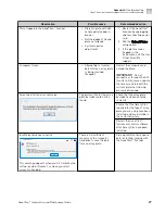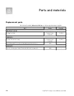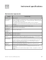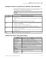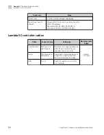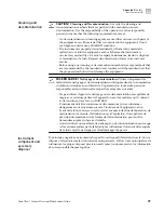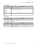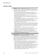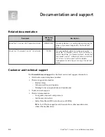
Electrical requirements
CAUTION!
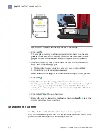
Do not unpack or plug in any components until they are configured
for the proper operating voltage by the service representative.
WARNING!
For safety, the power outlet for the instrument must be accessible
at all times. See “Component clearances required for installation and
maintenance“ on page 31 for information about the space needed between the
wall and the instrument. In case of emergency, you must be able to immediately
disconnect the main power supply to all the equipment. Allow adequate space
between the wall and the equipment so that the power cords can be
disconnected in case of emergency.
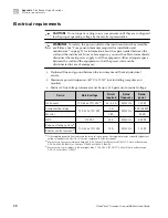
• Dedicated line and ground between the instrument and the main electrical
service.
• Maximum power dissipation: ~417 VA, 371 W (not including computer and
monitor)
• Mains AC line voltage tolerances must be up to ±10 percent of nominal voltage.
Device
Rated voltage
Circuit
required
Rated
frequency
Rated
power
Instrument
100–240 ±10% VAC
[1]
6.2–2.6 A
50/60 Hz
960 W
Computer (desktop)
100–240 ±10% VAC
6 A
50/60 Hz
825 / 685 W
Monitor
1.5 A
65 VA
UPS
110 VAC
20 A
50/60 Hz
980 W
Xenon arc lamp system
[2]
100–240 ±10% VAC
10 A
50/60 Hz
300 W
Shutter control system
[3]
[1]
If the supplied power fluctuates beyond the rated voltage, a power line regulator may be required. High or low
voltages can adversely affect the electronic components of the instrument.
[2]
Mains fuse in the rear of cabinet: 5 Amp, 250 V, 5 x 20 mm, Time Delay fuse EIC 60127-2 (such as Bussmann
GDC-5A, S506-5A (RoHS), or Littelfuse 218.005 or 218.005.P (RoHS))
[3]
Mains fuse in rear of cabinet: 5 x20 mm glass tube, T 1.0A, 250 V, IEC 60127-2, Sheet III (such as Bussmann
GDC-1A or LittelFuse 218 001)
Appendix C
Instrument specifications
Electrical requirements
C
30
GeneTitan
™
Scanner Use and Maintenance Guide

