background image

Component clearances required for installation and maintenance

During installation and maintenance, it is necessary to access the front, back, and right

side of the product. If the back of the product faces a wall, ensure that there is

sufficient clearance on the bench to rotate the product.

IMPORTANT! 

For safety reasons, the power outlet for the product must be accessible

at all times.

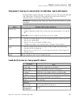
Bench

Minimum clearance and requirements

Requirements

• Level surface
• Capable of bearing the weight of the instrument system and components: 113.4 kg (250

lbs)

IMPORTANT! 

Air flow around the instrument must not be restricted.

Depth

• Must be at a minimum depth of ~79 cm (31 in.) deep to hold the instrument, xenon arc

lamp, monitor, and keyboard.

• Allow for 5.1 cm (2 in) in the back for proper airflow.
• If the bench has wheels, it can facilitate access to the back of the instrument.

Width

• Must be a minimum width of 142.2 cm (56 in.) for the instrument, xenon arc lamp,

computer, monitor, and keyboard.

• Allow for 30.5 cm × 30.5 cm (12 in × 12 in) of clearance to the left of the instrument for

array plate access.

Height

Must be a minimum of 76.2 cm (30 in.) height clearance.

Lambda LS xenon arc lamp specifications

Parameter

Value

Output range

320-700 nm (standard, ozone-free bulb)

Radiant output

50 watts (broadband, full beam) for 300 W bulb

Lamp type

300 W Xenon, pre-aligned to produce collimated output

Lamp life

Lamp warranted for 500 hours; expected lifetime is 500 hours

Dimensions (H x W x D) 10.5 x 9.5 x 10 inches (26.7 x 24.1 x 25.4 cm)

Weight

10.5 lb (4.8 kg)

Electrical

Mains voltage

110 through 240 V 50 through 60 Hz

Maximum power

consumption

300 W

Appendix C 

Instrument specifications

Component clearances required for installation and maintenance

C

GeneTitan

 Scanner Use and Maintenance Guide

31
Summary of Contents for GeneTitan Scanner

Page 1: ...For Research Use Only Not for use in diagnostic procedures GeneTitan Scanner USE AND MAINTENANCE GUIDE Catalog Numbers 00 0442 and 00 0443 Publication Number MAN0018315 Revision A 0...

Page 2: ...b No MAN0018315 Revision Date Description A 0 31 December 2019 New publication Important Licensing Information These products may be covered by one or more Limited Use Label Licenses By use of these p...

Page 3: ...Start the scanner 15 Scan an array plate 15 Shut down the scanner 16 CHAPTER 3 Maintain the Instrument 17 GeneTitan Maintenance 17 Monthly 17 Every six months 17 Lambda LS xenon arc lamp 18 Replace th...

Page 4: ...ety labels 35 Conformity symbols 36 Safety information for instruments not manufactured by Thermo Fisher Scientific 36 Instrument safety 36 General 36 Physical injury 37 Electrical safety 38 Cleaning...

Page 5: ...tan Scanner is also equipped with a filter slider that allows up to 2 optical filters sets to detect fluorescence intensity of samples in array plate layouts for downstream analysis Parts of the instr...

Page 6: ...arious patterns of light and color indicating different instrument conditions The following table defines the meaning for the status light patterns Light indicator Instrument status Solid green Ready...

Page 7: ...ation to receive or expel the array plate and scan tray combination 1 2 1 Scanner drawer door 2 Scanner drawer extended WARNING Crushing Injury Hazard Do not place hands or face near the load tray whe...

Page 8: ...guide connects to the Lambda LS CAUTION FireWire IEEE 1394 High Speed Serial Bus and USB cables are not locking connectors Ensure that the FireWire and USB cables are plugged securely and in the corr...

Page 9: ...network 6 USB 3 0 port connect to Kvaser USB cable from scanner 7 USB 2 0 port 1 spare 8 DVI and HDMI video ports connect to monitor 9 FireWire ports 2 connect one to scanner 10 Power cable connector...

Page 10: ...ens tube 3 Liquid light guide connect to the back panel of the scanner see the following caution note 4 Serial connection connect to the Lambda SC CAUTION The liquid light guide is a fragile fiber opt...

Page 11: ...o the back panel of the GeneTitan Scanner TTL OUT is not used in the GeneTitan Scanner System configuration 7 Serial port 9 pin DSUB female receptacle that establishes an RS 232 serial interface betwe...

Page 12: ...light source with shutter 5 1 2 7 8 4 3 6 1 Chassis ground connection screw 2 Outlets 3 USB B type port 4 UPS monitoring port 5 Battery connector 6 Input circuit breaker 7 Controlled outlet group 8 U...

Page 13: ...schedule these activities for those times when you are not imaging arrays Never push an object into the instrument ventilation slots as it can cause equipment damage or personal injury Do not set any...

Page 14: ...inutes to warm up the lamp In standby mode the lamp remains on for 1 hour before it is automatically switched off The automatic shutdown of the lamp is by design and is intended behavior Do not try to...

Page 15: ...epending on the status of the scan workflow 1 2 3 4 5 6 1 Start 2 Load 3 Unload Plate 4 Stop 5 Email Settings 6 Help 1 Check the remaining lamp life under System Status in the upper left of the GeneTi...

Page 16: ...lick Start 7 Click OK in the Start Processing confirmation window to continue Scanning proceeds When the scan is complete color coded results are displayed in the array graphic in the System Status se...

Page 17: ...rviceable parts inside the scanner housing Contact Thermo Fisher Scientific to schedule qualified field service personnel to replace all internal parts CAUTION Do not attempt to service the instrument...

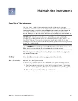
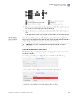
Page 18: ...ack of the lamp A spare fuse is also provided in the power input module WARNING Replace fuse with the same type and rating 5 Amp 250 V 5 x 20 mm time delay fuse EIC 60127 2 1 Unplug power cord from th...

Page 19: ...re application alerts you to the requirement to replace the lamp The lamp replacement procedure is simple but good health and safety precautions must be followed CAUTION Do not try to replace the lamp...

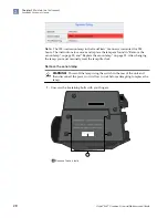
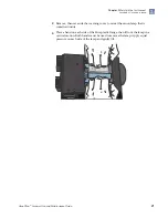
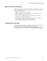
Page 20: ...hanging the lamp you must manually reset the lamp life clock Remove the xenon lamp WARNING Power off the lamp using the switch in the rear of the unit and then disconnect the power cord Allow to cool...

Page 21: ...hand on each side of the blue plastic flange then lift out the lamp in a vertical motion Both hands must be used to remove the lamp Apply equal pressure on each side of the lamp and gently lift Chapte...

Page 22: ...tic flanges Ensure that the lamp bulb faces inward toward the rear heat sink on the unit and then vertically lower the lamp to install 1 2 1 Xenon bulb faces away from the fan and towards the heat sin...

Page 23: ...he lamp counter are reset This menu option is only available when the system is not active 1 Select Tools4Reset Lamp Life Time 2 Read the confirmation message that appears then confirm that all condit...

Page 24: ...ily visible in the fuse holder when you take it out is the one that is active when the holder is installed A spare fuse is also stored within the fuse holder as shown following 1 5 2 6 7 4 3 1 Lambda...

Page 25: ...g with date and time code Text file with info on use of the Library File Importer The following GCC files and requests are sometimes used by FAS or FSE for troubleshooting Library files PARAMS MASTER...

Page 26: ...e same error occurs close the application and power off the computer and then restart If the error still occurs power off the GeneTitan Scanner and then restart Observation Possible cause Recommended...

Page 27: ...e has been entered correctly Ensure that the library files required for the type of array plate you are using have been installed and are installed in the correct directory Restart the GeneTitan Instr...

Page 28: ...rce Cat No GeneTitan Scanner Cooling Fan Filter Thermo Fisher Scientific 01 0785 Lambda LS Cermax Xenon Arc Lamp Thermo Fisher Scientific 01 0740 Fuse 5 Amp 250 V 5 20 mm time delay fuse EIC 60127 2 M...

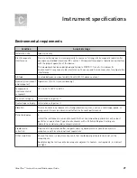
Page 29: ...o 30 C 59 F to 85 F Transient category Installation categories II Overvoltage category Installation categories II Vibration The instrument is not adjacent to strong vibration sources such as a centrif...

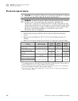
Page 30: ...or Mains AC line voltage tolerances must be up to 10 percent of nominal voltage Device Rated voltage Circuit required Rated frequency Rated power Instrument 100 240 10 VAC 1 6 2 2 6 A 50 60 Hz 960 W C...

Page 31: ...bench has wheels it can facilitate access to the back of the instrument Width Must be a minimum width of 142 2 cm 56 in for the instrument xenon arc lamp computer monitor and keyboard Allow for 30 5 c...

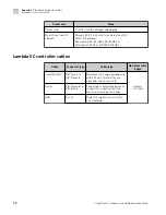
Page 32: ...le type Maximum cable length SmartShutter DB 9 male to DB 9 female Minimum of 26 awg stranded wire with 500 volt Two ferrites are attached one at each end 3 meters 10 feet Serial DB 9 female to DB 9 m...

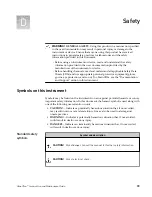
Page 33: ...DSs see the Documentation and Support section in this document Symbols on this instrument Symbols may be found on the instrument to warn against potential hazards or convey important safety informatio...

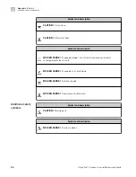
Page 34: ...res renseignements de s curit MISE EN GARDE Risque de choc lectrique MISE EN GARDE Surface chaude MISE EN GARDE Rayonnement ultraviolet Symbol and description CAUTION Moving parts Symbole et descripti...

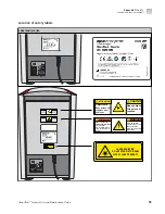
Page 35: ...wo person lift required WARNING AVERTISSEMENT ONLY authorized personnel may service this equipement See manual for safety information SEUL le personnel autoris peut intervenir sur ce mat riel Voir les...

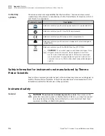
Page 36: ...al waste ordinances for proper disposal provision and contact customer service for information about responsible disposal options Safety information for instruments not manufactured by Thermo Fisher S...

Page 37: ...ur torso at the same time Keep your spine in a good neutral position while lifting with your legs Participants should coordinate lift and move intentions with each other before lifting and carrying Fo...

Page 38: ...e la terre et de puissance ad quate S assurer que la tension lectrique est convenable Ne jamais utiliser l instrument alors que le dispositif de mise la terre est d connect La continuit de la mise la...

Page 39: ...eur ou toute autre personne responsable est tenu d assurer le respect des exigences suivantes Ne pas utiliser d agents de nettoyage ou de d contamination susceptibles de r agir avec certaines parties...

Page 40: ...ntact The following table lists laser safety symbols and alerts that may be present on the instrument Alert CAUTION Class 2 II visible and or invisible laser radiation present when open and interlocks...

Page 41: ...1 Equipment classification and requirements EMC standards Reference Description EU Directive 2014 30 EU European Union EMC Directive Environmental design standards Reference Description Directive 2012...

Page 42: ...ysis if needed the waste generated by the particular applications reagents and substrates used in your laboratory Ensure that the waste is stored transferred transported and disposed of according to a...

Page 43: ...ons peuvent s appliquer leur limination Biological hazard safety WARNING BIOHAZARD Biological samples such as tissues body fluids infectious agents and blood of humans and other animals have the poten...

Page 44: ...intuitive set of tools for instrument control and data management used in the processing of GeneChip arrays Customer and technical support Visit thermofisher com support for the latest service and sup...

Page 45: ...nt has been penetrated by water If after service or calibration the instrument does not perform in accordance with the capabilities that are stated in the specifications If the instrument has been dro...

Page 46: ...thermofisher com support thermofisher com askaquestion thermofisher com 31 December 2019...

Reviews: