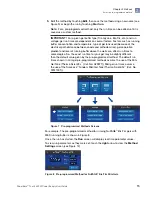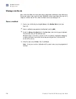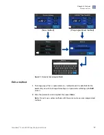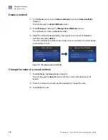
Real time output parameters
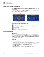
Electrical output parameters (A, V, and W) will be displayed in real time in a bar
at the bottom of the screen. The method parameter being held constant will be in
highlighted font.
Crossover indicator
When electrical output is limited by a non-constant method parameter or by a power
supply output maximum, the automatic crossover feature is activated. The crossover
icon ( ) will then be displayed to the right of the new limiting parameter and that
parameter will be in highlighted font.
As an example: If the method uses constant voltage of 200 V, but the power supply
reaches 3 A (the power supply maximum) before 200 V is reached, the power supply
will automatically switch to a constant current of 3 A with the voltage floating. If at
some point conditions of the run change (resistance increases and current drops)
such that 200 V can be delivered with less than the power supply maximum current
(3 A), the power supply will automatically revert back to the set method constant
parameter (200 V in this case) and the crossover icon will no longer be displayed.
Figure 12 shows a run with crossover to A and current limited to 0.04 A. For
additional details, see Appendix A, “Troubleshooting”.
Stop and Pause buttons
The run can be stopped or temporarily paused by touching
Stop
or
Pause
. The
method can be edited when paused.
Right navigation arrow
Touch this arrow to display the
Method Settings
screen (Figure 12). This screen
shows parameter settings for the step currently being run. From this screen, touch
the
left
arrow to return to the
Run
screen.
Method Settings screen features
The
Method Settings
screen (see Figure 12) displays voltage, current, power, and
run time for the method. Time is shown in hours : minutes format. If the method has
more than one step, there will be a separate method screen for each step. Use the
right
and
left
arrows to move between screens for individual steps.
Note:
Method settings are not real-time numbers. They do not change during the
run. Real-time run parameters are shown on the
Run
screen.
Chapter 2
Methods
Instrument display during a run
2
PowerEase
™
Touch 350W Power Supply User Guide
21
Summary of Contents for Invitrogen PowerEase Touch PS0350
Page 37: ......

