23
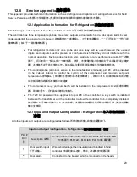
12.0 Service Appendix
服务附录
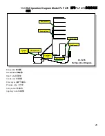
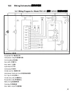
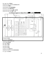
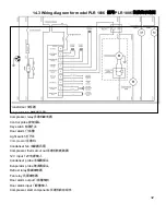
This appendix provides technical information such as a refrigeration diagrams and wiring schematics for Field
Service Personnel.
本附录为现场服务人员提供了诸如制冷图和接线示意图等技术信息。
12.1 Application Information for Refrigerators
冰箱应用信息
The following is a description of how the controller is used.
以下说明了如何使用控制器。
The controller has three temperature probes, three relay outputs, a door switch and a door open alarm buzzer
(independent of the general alarm buzzer).
控制器有三个温度探头,三个继电器输出,一个门开关和一个开门报
警蜂鸣器(独立于一般报警蜂鸣器)。
•
For refrigerator models only one probe and one relay will be used however the unused
inputs and outputs must be present or configured such that they do not interfere with the
normal operation. Moving probe location voids warranty or any performance claim.
对于冰箱
型号,将只使用一个探头和一个继电器,然而,未使用的输入和输出端子必须备好或妥善安
置,并使其不会干扰正常的运作。移动探头位置将导致保修或任何性能索赔无效。
•
The control probe (cold-room sensor in the manufacturer’s manual), port #6, will be installed
in the cabinet interior to control the cycling of the compressor and maintain set point
temperature.
控制探头(制造商手册中的冷冻室传感器),即端口#
6
,将被安装在机柜内部,
以控制压缩机的循环并维持设定温度。
•
The compressor relay, port number 5, will be installed in the compressor circuit.
压缩机继电
器,即端口号
5
,将安装在压缩机电路内。
•
The 12V AC power will be supplied into port #9 of the controller; a key switch is installed
between the transformer and the controller to allow the controller to be completely disabled.
控制器的
9
号端口将接入
12V
交流电源,变压器和控制器之间将设有钥匙开关,使控制器能
够完全禁用。
12.2 Input and Output Configuration - Refrigerators
输入和输出配置
-
冰箱
All other inputs and outputs are configured as follows.
所有其他的输入和输出配置如下。
Input and Output Configuration - Refrigerators
输入和输出配置
-
冰箱
Port #
端口
号
Description
说明
Configuration for Model Numbers PLR 221, PLR 386, PLR
1006,
型号
PLR 221, PLR 386, PLR 1006
的配置
1
Door switch input
门开关输入
Wires shorted together, insulated and bundled behind
controller
电源线接头连接,绝缘,并绑在控制器后面
2
Door alarm
Connected to the buzzer which is mounted on the header

