background image


所有的指示,并按照铭牌上注明的设计范围进行操作。


4.1  Location

安装位置


Install the unit in a level area free from vibration with a minimum of 10cm of space on the sides and top and 

15cm at the back of the unit.  See the install space dimensions below in section 4.2.

将设备安装在一块平整的无

振动场地,设备两侧及顶端应最少保留

10

厘米的空间,背面最少保留

15

厘米的空间。


见下文第

4.2

条:安装

空间尺寸。


Do not position the equipment in direct sunlight or near heating diffusers, radiators, or other sources of heat. 

The ambient temperature range must be between 15°C and 32°C.

设备不要放置在阳光直射或靠近加热扩散器、

散热器或其他热源的地方。


环境温度范围必须在

15°C-32°C


4.2  Install Space Dimensions

安装空间尺寸


Allow adequate space around the unit after installation to provide for airflow.  Be certain to allow for door 

swing, and doors with handles must be capable of opening at least 85 degrees from the closed position without 

touching an adjacent wall.  The table below shows the required clearance dimensions.

设备安装后周围须留有足

够的空间允许气流通过。务必留出门的摆动空间,带把手的门须至少能够从关闭位置打开到

85 

度且不会碰到相

邻的墙面。下表显示了必需的间隙尺寸。


Minimum Clearance Areas 

最小间隙区域


Model PLR 221 

and PLR 1006 

型号

PLR221

PLR 1006 

Model PLR 386 

型号

PLR 386 

Model PLF 276 

型号

PLF 276 

Minimum Clearance  – Top

顶部最小

间隙


10 cm (min)

(最小

尺寸)


10 cm (min)

(最

小尺寸)


10 cm (min)

(最小尺寸


Minimum Clearance  – Side, 

两侧最

小间隙


10 cm (min)

(最小

尺寸)


10 cm (min)

(最

小尺寸)


10 cm (min)

(最小尺寸


Minimum  Clearance  – Back, Free 

Standing, 

自由站立时背面最小间隙


15 cm (min)

(最小

尺寸)


15 cm (min)

(最

小尺寸)


15 cm (min)

(最小尺寸


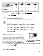
Table 3 Clearance Dimensions

3

间隙尺寸


4.3  Operational/Field Environment

操作

/

现场环境


The table below displays the Operational/Field Environment

下表显示了显示操作

/

现场环境


Summary of Contents for PLF 276

Page 1: ...Installation and Operation Manual Thermo Scientific Laboratory Refrigerators and Freezers...

Page 2: ...2 All trademarks are the property of Thermo Scientific Inc and its subsidiaries 2011...

Page 3: ...276 Input power w 170 450 720 340 Rated voltage v 220 220 220 220 240 Rated Current A 1 1 3 6 5 2 Ambient temperature 15 32 15 32 15 32 10 32 Inner temperature 0 10 0 10 0 10 10 40 Net weight kg 58 94...

Page 4: ...1 6 0 User Interface Refrigerators 11 6 1 Custom User Interface Refrigerators 11 6 2 User Interface Operation Refrigerator 12 7 0 Service Parts Lists Refrigerators 13 8 0 Application Information for F...

Page 5: ...agram Model PLF 276 PLF 276 28 14 0 Wiring Schematics 29 14 1 Wiring Diagram for Model PLR 221 PLR 221 29 14 2 Wiring Diagram for Model PLR 386 PLR386 30 14 3 Wiring diagram for model PLR 1006 PLR 100...

Page 6: ...ent equipment Any modification or use of this equipment in a manner other than expressly intended may cause death or serious injury This includes use of user supplied components and materials not spec...

Page 7: ...the equipment within five days of delivery If you find any damage keep the packing materials and immediately report the damage to the carrier Do not return goods to Thermo Scientific without written...

Page 8: ...r installation to provide for airflow Be certain to allow for door swing and doors with handles must be capable of opening at least 85 degrees from the closed position without touching an adjacent wal...

Page 9: ...y cause personal injury or damage to the equipment Always conform to the local codes Do not connect unit to already overloaded power lines Refrigerator and freezer units use 10 or 16 amp power cords T...

Page 10: ...ers A loose fitting gasket allows moist air to be drawn into the cabinet resulting in quicker frost buildup on the evaporator coil longer running time poor temperature maintenance and increased operat...

Page 11: ...rigerators 6 1 Custom User Interface Refrigerators The figure below shows the user interface for refrigerator models PLR 221 PLR 386 PLR 1006 PLR 221 PLR 386 PLR 1006 To operate the unit the key must...

Page 12: ...the key to the ON position the cabinet temperature will be displayed and the unit will begin to refrigerate ON Turn the key to the OFF position the display will be blank and refrigeration will stop t...

Page 13: ...art Part Description 316516G01 Header Panel Weld Assembly 316677G01 Header Panel Assembly 316504H01 Control Board Assembly 316504H01 Control Board Assembly 306300300 Keps Nuts Keps 316520H01 Control B...

Page 14: ...uts Keps PLR 386 Service Parts List PLR 386 Part Description 316517G01 Header Panel Assy 65921H01 Caps 306300300 Keps Nuts Keps 3000000256 Compressor 316496H01 Compressor relay harness PLR 386 Service...

Page 15: ...1 Press the Set button once and Set High Temperature icon lights Set Set High Temperature 2 Press the Press the button or the button to set High Temperature Alarm High Temperature Alarm Complete the...

Page 16: ...or decrease the Control Temperature Confine limits Control Temperature Confine Battery backup charge switch location and dry contact location 1 To charge the battery that is used to back up controller...

Page 17: ...mperature press the button or the button 4 After reaching the desired temperatur setting press the Set button Set The indicator light for Temperature Setting and the Adjusted Sensor Temperature displa...

Page 18: ...TEMPERATURE window E0 Pulse noise On Table 6 Alarm Functions 6 Note Press the Alarm Test button to turn off the buzzer Alarm Test The battery can supply power to the alarm for 18 24 hours in case of...

Page 19: ...binet with a solution of one liter of warm water and thirty milliliters of baking soda Wash the outside with a mild detergent such as dishwashing liquid Do not use harsh or abrasive cleaners When the...

Page 20: ...uum 3 Make certain the door gasket does not have gaps or leaks Re seat or replace the gasket if worn 4 Make sure the optimum running temperature is set correctly and not set too low 5 Verify that the...

Page 21: ...ion extends to subsequent owners During the first twenty four 24 months component parts proven to be non conforming in material or workmanship will be repaired or replaced at Thermo Scientific s expen...

Page 22: ...RITTEN ORAL OR IMPLIED NO WARRANTIES OF MERCHANTABILITY OR FITNESS FOR A PARTICULAR PURPOSE SHALL APPLY Thermo shall not be liable for any indirect or consequential damages including without limitatio...

Page 23: ...The control probe cold room sensor in the manufacturer s manual port 6 will be installed in the cabinet interior to control the cycling of the compressor and maintain set point temperature 6 The comp...

Page 24: ...controller Defrost relay is not installed 5 Compressor relay output Connected to compressor relay which is mounted on the header panel 6 Control probe input Connected and installed in the interior of...

Page 25: ...l Only 00 E4 Compressor start delay time 02 H3 For Service Personnel Only 00 E5 Offset on cabinet temperature 00 C2 High temperature alarm 07 E6 Offset on evaporator temperature 00 C3 Low temperature...

Page 26: ...r Fin tube type Capillary tube Suction tube Condenser Evaporator Fin Tube Type Capillary Tube Suction Tube Process Tube Filter Dryer Condenser Wire Tube Type Compressor PLR 386 and PLR 1006 Refrigerat...

Page 27: ...Diagram for PLR 221 PLR 221 Capillary tube Suction line Evaporator Plate Type Condenser Filter dryer Process tube Compressor Note arrows point the direction of refrigerant flow Compressor Note Arrows...

Page 28: ...PLF 276 PLF 276 Evaporator Accumulater Halo Tube Condenser Filter dryer Process tube Compressor Capillary tube PLF 276 Refrigeration Diagram Compressor Evaporator Capillary Tube Process Tube Filter Dr...

Page 29: ...el PLR 221 PLR 221 Transformer Evaporator fan Compressor relay Control probe Key switch Door alarm Light switch Compressor Condenser fan Compressor thermal cut out 12V input 12V Condenser probe Evapor...

Page 30: ...output Unused fan output Unused door open buzzer Unused door open input 14 2Wiring Diagram for Model PLR 386 PLR386 Transformer Evaporator fan Compressor relay Control probe Key switch Door alarm Lig...

Page 31: ...probe Defrost relay Fan relay Door alarm output Door alarm input Compressor start components Unused probe Unused defrost output Unused fan output Unused door open buzzer Unused door open input Horizon...

Page 32: ...aporator fan Compressor relay Control probe Key switch Door alarm Light switch Compressor Condenser fan Compressor thermal cut out 12V input 12V Condenser probe Evaporator probe Defrost relay Fan rela...

Page 33: ...33 Unused probe Unused defrost output Unused fan output Unused door open buzzer Unused door open input...

Page 34: ...above information can be found on the data plate attached to the equipment If available please provide the date purchased the source of purchase Thermo or specific agent rep organization and purchase...

Reviews: