4.3
Positioning and Installation .
INFORMATIONS
The protective devices of the series PROLINE being relatively simple products , are
delivered ready for use , after proper installation. It is however advisable to carry
out the placement , installation and electrical connection to qualified personnel.
The equipment, mechanical and electrical , needed for placement and installation are as
follows :
• Spirit level
• Keys Traditional
• Common tools
• Multimeter
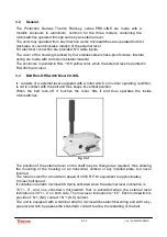
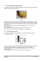
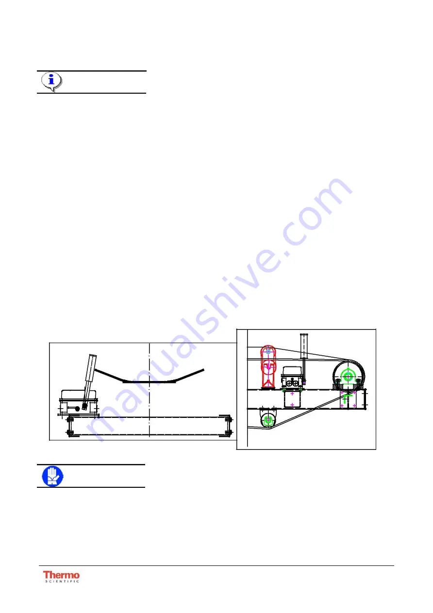
4.3.1 Belt Run-Off Switch Mod. 60-30G.
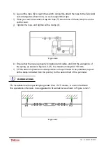
The Belt Run-off Switch is normally installed on both sides of the belt near the drum head
and tail. For belts of particular extension , there should be of flags even along the ribbon ,
each 200 meters about, and immediately after the loading points . The unit must be
installed at a distance from the belt such that the roller lever is angled 30 degrees when
the belt is in the position required for the block. In normal condition the belt should not
touch the roller lever.
Fig. 4-3-1
WARNING
The device should never be installed with the roller lever upside down, as
the weather and dirt can damage the bearings.
12 / 30
Cod.: PL-000603X-D002G
Summary of Contents for PRO-LINE 60-30G
Page 25: ...8 ANNEX 25 30 Cod PL 000603X D002G ...
Page 26: ...26 30 Cod PL 000603X D002G ...
Page 27: ...27 30 Cod PL 000603X D002G ...
Page 28: ...28 30 Cod PL 000603X D002G ...
Page 29: ...29 30 Cod PL 000603X D002G ...
Page 30: ...30 30 Cod PL 000603X D002G ...


