h) Lay out the rope
(5)
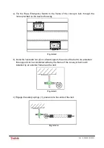
to reach the switch; during this attach the rope to the helicoidal
nuts arranged as shown in d), so as to support the rope.
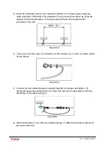
i) Once you reach the switch, wrap the rope
(5)
around one of these two pins on the
control lever.
j) Tighten the rope, and tighten with a clamp
(3).
Fig. 4-3-2-6
k) Ensure that the rope is properly tensioned and visible, and limit the elongation of
the spring, as shown in figure 4-3-2-5, to a maximum length of 180 mm.
l) l) If the switch is placed in central position to the perimeter to be protected, repeat
all the steps indicated from the point e) for the second half of the perimeter.
INFORMATIONS
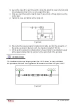
For installations with ropes lengths greater than 10-15 meters, in order to facilitate
the operations of tension, it is suggested to fit a stretcher as shown in Figure 4-3-2-7.
Fig. 4-3-2-7
17 / 30
Cod.: PL-000603X-D002G
Summary of Contents for PRO-LINE 60-30G
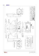
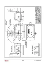
Page 25: ...8 ANNEX 25 30 Cod PL 000603X D002G ...
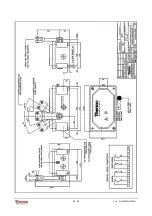
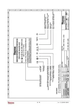
Page 26: ...26 30 Cod PL 000603X D002G ...
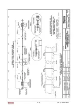
Page 27: ...27 30 Cod PL 000603X D002G ...
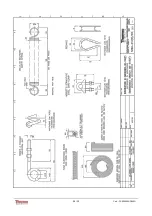
Page 28: ...28 30 Cod PL 000603X D002G ...
Page 29: ...29 30 Cod PL 000603X D002G ...
Page 30: ...30 30 Cod PL 000603X D002G ...

