Thermo Scientific Revco Cryogenic Storage Freezers
Installation and Operation
6
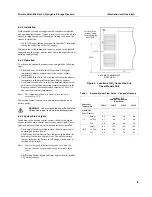
6.3.2 Installation
Field installed systems are supplied with complete installation
and operating instructions. If your system is factory installed, the
freezer is shipped with a coiled length of tubing to connect the
freezer to the bottles:
•
5/8 in. OD copper tubing covered with Armaflex
™
insulating
tubing for connection to the LN
2
supply.
Straighten the coiled tubing and connect one end to the labeled
connection on the freezer and the other end to the supply bottle or
building supply fitting.
6.3.3 Operation
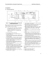
To activate the optional backup system, complete the following
steps:
1. Push the Power Switch to the ON position. The digital
temperature display window shows the current cabinet
temperature.
2. Press and hold the Push to Set button to display the setpoint
temperature in the digital temperature display window.
3. Use a small screwdriver to rotate the Setpoint Adjust screw
until the correct backup operating temperature shows in the
display window. The recommended setpoint is 10 to 15
°
C
above normal cabinet temperature.
Note:
The temperature shown in the display window is
accurate to
±
1
°
C.
The backup system can run for a minimum of eight hours on
battery power.
WARNING!
You must push the Power Switch to the
ON position in order to activate the backup system.
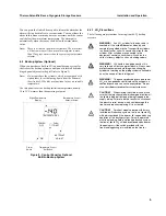
6.3.4 System Status Lights
In addition to the backup control system, the built-in backup
system includes main control panel system status lights. These
lights are only available when the backup system is installed.
•
The Supply On Indicator lights when the backup system is
operating on battery power.
•
The Backup System Battery Low Indicator lights when the
backup system battery charge is low. The built-in battery
charger recharges the battery to full charge when power is
restored to the system.
Note:
Since rechargeable batteries degrade over time, the
battery should be replaced after approximately three
years.
•
The Backup System Empty Indicator lights when the standby
LN
2
bottle is empty.
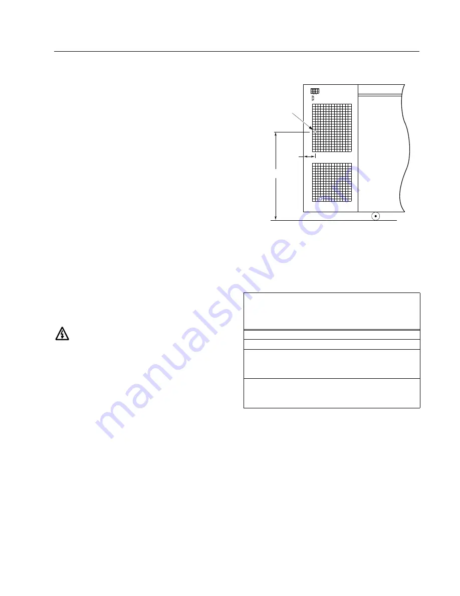
Figure 4. Location of LN
2
Connection Site,
Chest Models Only
Table 1.
Backup System Flow Rates – Cryogenic Freezers
Lbs/hr @ 75
×
F
Ambient Temperature
(Flow Rate)
Center Air
Temperature
-150
×
C
-140
×
C
-130
×
C
-120
×
C
Liquid LN
2
Chest Freezers
7 ft
3
Empty
11.3
10.0
9.0
8.0
1/2 Full
9.7
8.6
7.6
6.8
Full
7.8
6.8
6.0
5.2
10 ft
3
Empty
15.2
13.5
11.9
10.3
1/2 Full
12.0
10.4
9.4
8.3
Full
8.9
7.8
7.0
6.1
24.75"
2.375"
LN
2
Inlet Conn.
Copper Tubing
Factory Supplied
0.625" O.D.
MACHINE COMPARTMENT
REAR VIEW

