Thermo Scientific Revco Cryogenic Storage Freezers
Installation and Operation
8
8 Chart Recorders
Panel-mounted six-inch seven-day recorders are available as
options for all freezer models.
8.1 Set Up and Operation
To prepare the recorder to function properly, complete the
following steps:
1. Open the recorder door to access the recorder.
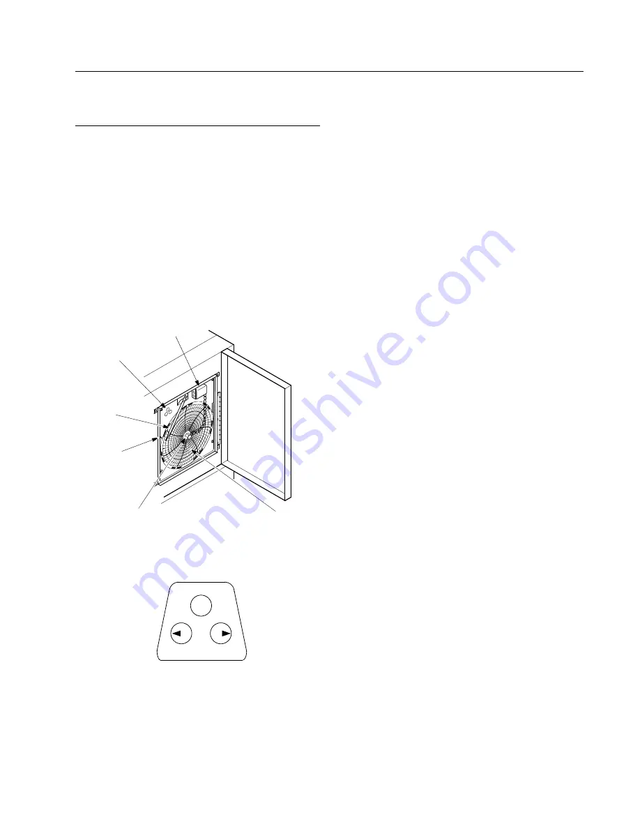
2. Connect the nine volt DC battery located at the recorder’s
upper right corner. This battery provides backup power.
3. Install clean chart paper (refer to Section 8.3 below).
4. Remove the plastic cap from the pen stylus and close the
recorder door.
Recorder operation begins when the system is powered on.The
recorder may not respond until the system reaches temperatures
within the recorder’s range.
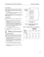
Figure 5. Chart Recorder
Figure 6. Chart Buttons
8.2 Power Supply
The recorder normally uses AC power when the system is
operating. If AC power fails, the LED indicator flashes to alert
you to a power failure. The recorder continues sensing cabinet
temperature and the chart continues turning for approximately
24 hours with back-up power provided by the nine-volt battery.
The LED indicator glows continuously when main power is
functioning and the battery is charged.
When the battery is low, the LED flashes to indicate that the
battery needs to be changed.
8.3 Changing Chart Paper
To change the chart paper, complete the following steps:
1. Locate the pressure sensitive buttons at the front, upper left
of the recorder panel.
2. Press and hold the Change Chart button (#3) for one second.
The pen will move off the scale.
3. Unscrew the center nut, remove the old chart paper, and
install new chart paper. Carefully align the day and time with
the reference mark (a small groove on the left side of the
recorder panel).
4. Replace the center nut and hand tighten. Press the Change
Chart button again to resume temperature recording.
8.4 Calibration Adjustment
This recorder has been accurately calibrated at the factory and
retains calibration even during power interruptions. If required,
however, adjustments can be made as follows:
1. Run the unit continuously at the control setpoint temperature.
Continue steady operation for at least two hours to provide
adequate time for recorder response.
2. Measure cabinet center temperature with a calibrated
temperature monitor.
3. Compare the recorder temperature to the measured cabinet
temperature. If necessary, adjust recorder by pressing the left
(#1) and right (#2) chart buttons.
Note:
The stylus does not begin to move until the button is held
for five seconds.
If you find that the recorder frequently needs to be calibrated
after paper changes, the program may have changed. To confirm
that the program is correct:
1. Press button #3 and allow the pin to move off the scale.
2. Press #1 for 10 seconds and release.
3. Confirm that the green LED flashes 3 times followed by a
pause. If the number of blinks is greater than or less than 3,
adjust the number using the left (#1) and right (#2) chart
buttons.
4. When the green LED blinks 3 times to confirm the resetting,
press the #3 button. The pin arm should then return to
indicate the current temperature. Repeat Steps 1-3 if
necessary.
9 Volt Battery
I
mprinting
Stylus
Hub-Nut and
Retaining Wire
Chart
Chart Buttons
Reference
Mark
1
2
3
CHANGE CHART

