Thermo Scientific Revco Cryogenic Storage Freezers
Installation and Operation
3
6 Operation
6.1 Control Panel Features
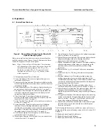
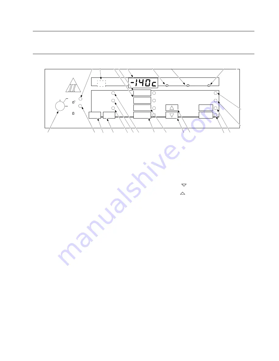
Figure 2. Revco Ultima II Series Control Panel with
Optional Backup System
Before the initial start up, take some time to become familiar
with the controls on your freezer. Figure 2 illustrates the Revco
Ultima II Cryogenic Freezer control panel.
Note:
Figure 2 shows all possible functions. These functions
vary depending on the options. You may not have all of
the functions on your equipment. The CO
2
or LN
2
Backup System lights (20, 21, 22) represent status
indicators for a built-in CO
2
or LN
2
backup system,
which is optional
.
1. Three position keyed Power On Switch.
2. Power On Indicator. This indicator lights when power is
connected to the freezer.
3. Temperature Failure Indicator. This indicator lights when the
freezer temperature deviates either above or below the alarm
temperature settings.
4. Power Failure Indicator. This indicator lights when there is a
power failure to the freezer (refer to Section 7 on page 7).
5. Life-Guard Alert Indicator. This indicator lights when the
first stage compressor has gone into a cautionary state of
operation to help prevent failure.
6. Check Fuse Light. This indicator lights when the surge
protector on the main electronic panel is blown by a power
surge (refer to Section 7 on page 7).
7. Alarm Test Pad. Press this pad to start an alarm test (refer to
Section 5.2.5 on page 6).
8. Alarm Reset Pad. Press this pad to reset
slowly
blinking
indicators. Slowly blinking indicators denote that the
condition
has
occurred but is now within the given operating
parameters. This pad is also depressed to temporarily silence
the audible alarm (refer to Section 5.2.4 on page 5).
9. Cold Alarm Setpoint. Press this pad to set the cold alarm
(refer to Section 6.2.3 on page 4).
10. Warm Alarm Setpoint. Press this pad to set the warm alarm
(refer to Section 6.2.3 on page 4).
11. Control Setpoint. Press this pad to set the cabinet temperature
(refer to Section 6.2.2 on page 4).
12. Cabinet Temperature Indicator. This indicator lights when the
temperature display window is showing the cabinet
temperature (refer to Section 6.2.1 on page 4).
13. Digital Temperature Display Window. This window displays
chamber temperature, alarm values, etc. depending on the
operating status of the freezer and the procedure being
performed.
14. Decrement Pad (
). Use this pad to decrease temperature
values.
15. Increment Pad (
). Use this pad to increase temperature
values.
16. Extreme Ambient Alert. This indicator lights when the
ambient temperature has exceeded the upper limit of the
recommended operating range. If the Extreme Ambient Alert
is activated, the ambient environment needs to be improved
for proper function of the freezer.
17. Clean Filter Indicator. This indicator lights when the air
cooled condenser filter is dirty (refer to Section 7 on page 7).
18. Alarm Battery Low Indicator. This indicator lights when the
charge on the alarm battery is low. Press this button to
display the percent of full battery charge in the digital display
window.
19. Voltage Boost Indicator. This indicator lights when incoming
voltage is low and the Voltage Safeguard has been activated
(refer to Section 7 on page 7). Press this pad to display the
current line voltage in the digital display window.
23. Alarm On/Set Point Security Indicator. This indicator lights
when the alarm is activated.Also indicates that Setpoint
Security is activated.
The following indicators are available only when the freezer is
equipped with the optional backup system (refer to Section 6.3.4
on page 6).
20. Backup System Supply On Indicator.
21. Backup System Empty Indicator
22. Backup System Battery Low Indicator.
off
life-guard alert
extreme ambient alert
clean filter
power failure
temperature failure
alarm testalarm reset
cabinet
temperature
control
set point
alarm
battery low
voltage
warm alarm
set point
cold alarm
set point
power on
alarm on
set point security
Ultima
1
15
7
9
10
11
SUPPLY
ON
SUPPLY
EMPTY
BACKUP SYSTEM
BATTERY
LOW
8
23
6
12
13
21
20
22
14
18
19
17
16
2
5
4
3
check
fuse
boost

