background image

Cryogenic Storage
Freezers

Installation and Operation 

325440H01 Rev. A


December


2013

Visit us online to register your warranty

www.thermoscientific.com/labwarranty

Summary of Contents for ULT-10140-9-D

Page 1: ...Cryogenic Storage Freezers Installation and Operation 325440H01 Rev A December 2013 Visit us online to register your warranty www thermoscientific com labwarranty...

Page 2: ...med by qualified service personnel Material in this manual is for informational purposes only The contents and the product it describes are subject to change without notice Thermo Fisher Scientific ma...

Page 3: ...specifications in this document supersede all previous information received by the purchaser Thermo Fisher Scientific Inc makes no representations that this document is complete accurate or error free...

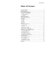
Page 4: ...n 6 Wiring 6 Leveling 7 Operation 8 Control Panel Features 8 Initial Loading 10 Start Up 11 Frame Heater Switch 14 Backup System Optional 15 Maintenance and Troubleshooting 19 Condenser Maintenance 19...

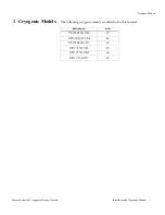
Page 5: ...orage Freezers Installation and Operation Manual 1 1 Cryogenic Models The following cryogenic models are described in this manual Model Number Suffix ULT 10140 9 D 19 ULT 10140 9 M 24 ULT 10140 9 V 23...

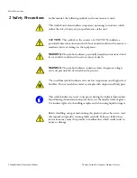
Page 6: ...avoided could result in serious injury or death WARNING This symbol indicates situations where dangerous voltages exist and potential for electrical shock is present The snowflake symbol indicates ext...

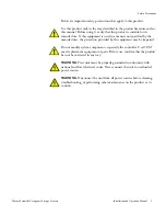
Page 7: ...nner not specified by the manufacturer the protection provided by the equipment may be impaired Do not modify system components especially the controller Use OEM exact replacement equipment or parts B...

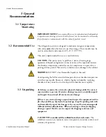
Page 8: ...time period This activity could also cause damage to the cabinet WARNING DO NOT store flammable liquids in this unit Avoid opening the lid for extended time periods since chamber temperature air will...

Page 9: ...relative humidity 60 for temperatures up to 32 C 90 F Main supply voltage fluctuations not to exceed 10 of the nominal voltage 4 1 Electrical Specifications The last character in the model number lis...

Page 10: ...open at least 90 degrees Do not position the equipment in direct sunlight or near heating diffusers radiators or other sources of heat The ambient temperature range at the location must be 59 to 77 F...

Page 11: ...the grounding prong from the service cord plug If the prong is removed the warranty is invalidated 5 3 Leveling The unit must be level both front to back and side to side To level chest models leave t...

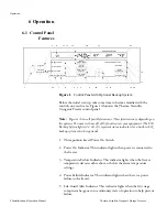
Page 12: ...Power On Indicator This indicator lights when power is connected to the freezer 3 Temperature Failure Indicator This indicator lights when the freezer temperature deviates either above or below the a...

Page 13: ...showing the cabinet temperature 13 Digital Temperature Display Window This window displays chamber temperature alarm values etc depending on the operating status of the freezer and the procedure being...

Page 14: ...stem Battery Low Indicator 6 2 Initial Loading After reading and completing the Safety Considerations Pre Inst0allation Installation and Operation sections of this manual turn the Key Switch to the PO...

Page 15: ...the Setpoint Security will be deactivated in this key position 3 The unit will start about 30 seconds later 6 3 2 Setting the Cabinet Temperature To set the cabinet temperature complete the following...

Page 16: ...int Security disabled 2 Press and hold the Warm Alarm Setpoint pad The LED next to this pad lights The temperature display shows the Warm Alarm value 3 Press and hold or to adjust the Warm Alarm Setpo...

Page 17: ...will decrease to approximately 15 times per minute The indicator will then remain flashing at this rate unless the condition reoccurs until the Alarm Reset button is pressed Once this has occurred th...

Page 18: ...n silence the alarm in this manner as many times as necessary until the sensor cools below the warm alarm temperature The alarm quits automatically when the sensor cools below the warm alarm value Not...

Page 19: ...re 3 Note Always purchase 22 psig supply cylinders and ensure that they are equipped with siphon tubes for withdrawing liquid from the bottom of the cylinder LN2 bottles are functional at any reasonab...

Page 20: ...re that the injection solenoid is energized to allow all the liquid to bleed off instead of being trapped in the supply tubing Failure to do this results in activation of the pressure relief device wh...

Page 21: ...40 C the backup system setpoint should be no colder than 135 C Note The temperature shown in the display window is accurate to 1 C The backup system can run for a minimum of eight hours on a fully cha...

Page 22: ...2 375 LN2 Inlet Conn Copper Tubing Factory Supplied 0 625 O D MACHINE COMPARTMENT REAR VIEW Table 1 1 Backup System Flow Rates Cryogenic Freezers Lbs hr 75 F Ambient Temperature Flow Rate Center Air T...

Page 23: ...he following steps 1 Pull the grill open 2 Remove the filter Check the fans If a fan is not operating contact an Authorized Service Company immediately 3 Vacuum the condenser using a soft brush attach...

Page 24: ...there is freezer odor wash the interior with a solution of baking soda and warm water Clean the exterior with any common household cleaner 7 Reinstall the sub lids close the lid restart the freezer a...

Page 25: ...leshooting Procedures Problem Details Check Fuse indicator is on Surge protector is blown Clean Filter indicator is on Condenser filter is dirty Refer to Section 7 1 on page 19 Alarm Battery Low indic...

Page 26: ...2 Connect the nine volt DC battery located at the recorder s upper right corner This battery provides backup power 3 Install clean chart paper refer to Section 8 3 below 4 Remove the plastic cap from...

Page 27: ...old the Change Chart button 3 in Figure 6 for one second The pen will move off the scale 3 Unscrew the center nut remove the old chart paper and install new chart paper Carefully align the day and tim...

Page 28: ...that the program is correct 1 Press button 3 in Figure 6 and allow the pin to move off the scale 2 Press 1 for 10 seconds and release 3 Confirm that the green LED flashes 3 times followed by a pause I...

Page 29: ...ts light bulbs and door gaskets are excluded from this warranty Replacement or repair of component parts or equipment under this warranty shall not extend the warranty to either the equipment or to th...

Page 30: ...eing performed Expendable items i e glass filters pilot lights light bulbs and door gaskets are excluded from this warranty Replacement or repair of component parts or equipment under this warranty sh...

Page 31: ...e information can be found on the dataplate attached to the equipment If available please provide the date purchased the source of purchase manufacturer or specific agent rep organization and purchase...

Page 32: ...Thermo Fisher Scientific Inc 275 Aiken Road Asheville NC 28804 United States www thermofisher com 3 3FW...

Reviews: