background image

Document 520/001 Rev 2.2 Dec 2013  

Page 4 of 10

Web

:  www.water­leak­detection.com   

E­mail

:   info@thermocable.com

Tel

:     +44 (0)1274 882359       

            Fax

:      +44 (0)1274 882229

ProH2O Water Leak Detection Application Guide

SENSOR CABLE INSTALLATION

Area Protection ­ Standard application

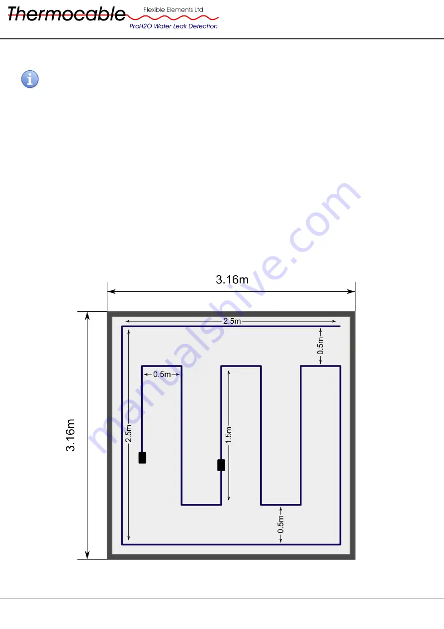
ProH2O sensor cable is ideally suited to detecting leaks over a wide area such as underneath a raised floor or 
similar applications. The sensor cable should be laid around the perimeter of the room and then spaced equally 
across  the  remaining  floor  space  as  shown  below. The  required  cable  length  can  be  approximately  calculated 
using the following formula:

Floor area (m

2

) + 10 


Minimum

 Cable Length (m)

Figure 1 shows the layout of ProH2O Sensor Cable when protecting an area of approximately 10m

2

. Here the 

sensor cable has first been laid around the perimeter of the room, no more than 0.5m away from the walls. The 
sensor  cable  is  then  laid  in  the  middle  of  the  room  at  a  0.5m  spacing  between  runs.  Using  standard  ProH2O 
sensor cable lengths, a 15m and 3.75m cable provide the required coverage. Depending upon the risk increase 
the coverage by reducing the spacing between cable runs and installing additional lengths of detection cable.

Figure 1. ProH2O Sensor Cable layout for Area Protection

Summary of Contents for ProH2O

Page 1: ...sdiction It is important at all times to keep the detection cable clean and free from dust debris and other contaminants that may soil the cable especially during installation Ensure any major constru...

Page 2: ...ks Air conditioning systems HVAC Early warning of leaks from HVAC pipes drip pans and other fittings High value property e g Historical Period buildings libraries museums Detect water leaks where a sm...

Page 3: ...l characteristics of the cable and signal an alarm or other action The sensor cable is available in pre terminated lengths for simple assembley and extension Non sensing pre terminated lengths are als...

Page 4: ...below The required cable length can be approximately calculated using the following formula Floor area m2 10 Minimum Cable Length m Figure 1 shows the layout of ProH2O Sensor Cable when protecting an...

Page 5: ...tact between the pipe and detection cable A maximum spacing of 150mm 6 is recommended between cable ties when the detection cable is attached to a pipe Adding lagging around the pipe over the detectio...

Page 6: ...roof space where there is a possibility of leaks going unnoticed for extended periods Typical examples include header tanks or expansion tanks in the loft of a house or in the roof space of an office...

Page 7: ...r cable can be laid around air conditioning units and the associated drip trays to provide an early warning of a malfunction or damage to the connecting equipment It is important to ensure the sensor...

Page 8: ...ntact with the water sensitive cores within the cable Figure 5 below shows the recommended mounting clips used to secure the sensor cable The clips shown hold the cable to the floor without any materi...

Page 9: ...to page 4 for examples 3 How can I check the integrity of the cable Each ProH2O System continuously monitors the cable for a fault anywhere along its length and emits a trouble signal if a fault occu...

Page 10: ...e is connected to Please refer to the ProH2O Module documentation Document No 550 001 or ProH2O Professional documentation Document 500 001 for more information It is worth noting that the ProH2O syst...

Reviews: