
Page 7 of 8 Revision 1.0 Mar 2020
ProReact EN Analogue Cable Test Kit Instructions
Document Ref. PACC-CTK
Operating Instructions contd.
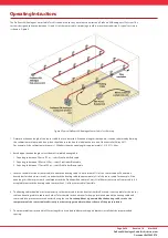
6. It may be preferable to temporarily secure the heating cable to the sensor cable using the provided tie wraps. Alternatively, it is
acceptable to temporarily attach the heating cable to the support brackets.
7. Once the heating cable has been fixed in place and the pipe insulation placed around the sensor cable and heating cable, plug the
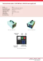
heating cable into the power supply unit on the front panel (see Figure 3). The heating cable plug pushes into the socket and then
twists clockwise to lock in place. To remove the heating cable pull the silver lever back on the plug and twist anti-clockwise.
8.
Before plugging the power supply unit into a suitable mains outlet, check the supply voltage switch on the rear panel of the
power supply unit is set to the appropriate voltage (either 240Vac or 120Vac)
. The supply voltage switch is set to 240Vac by
default. Use a flat screwdriver to turn the supply voltage switch to the correct setting. The power supply unit may be damaged if
the supply voltage switch is set incorrectly.
9. Plug the power supply unit into a mains supply, able to supply a minimum of 3A, using the supplied lead. If a different mains outlet
plug is required it may be sourced locally and connected into the power supply unit 3-pin C14 IEC socket on the rear panel.
10. Once the power supply unit has been plugged in it should power up and the red Stop button will be lit.
11. Ensure the heating cable is installed correctly. Any section of heating cable not installed around the sensor cable should be left in
open air and must not be covered up or overlap with other sections of the heating cable, which may result in overheating.
12. Where possible, it will aid testing of the ProReact EN Analogue system to reduce the chosen alarm temperature to the lowest
setting for the purpose of the test. For example, if the current alarm temperature setting is 100 deg C, for the duration of the
test the alarm temperature setting should be changed to 64 deg C or 54 deg C. The minimum alarm temperature setting will
depend upon the present ambient temperature of the sensor cable, a higher ambient temperature will necessitate a higher alarm
temperature. Refer to the ProReact EN Analogue installation and instruction manual for guidance. If the alarm temperature setting
was changed always return the setting to the original value once the test is completed.
13. Press the green Start button on the front panel of the power supply unit to start the test. The green Start button will light up
and the red Stop button light will turn off. The power supply unit supplies power to the heating cable for approximately 20
minutes, during which time the temperature around the sensor cable where the heating cable has been installed should increase
sufficiently enough to trigger an alarm.
14. After the green Start button has been pressed, check the ammeter on the power supply unit front panel to ensure the heating
cable is receiving power.
1. For the ProMinder Red cable the ammeter should show approximately 1A
2. For the ProMinder Blue cable the ammeter should show approximately 3A
3. For the ProMinder Brown cable the ammeter should show approximately 4.9A
If the ammeter does not show the correct value, press the red Stop button immediately and investigate why the current may
be incorrect (see troubleshooting section).
15. No further action needs to be taken with the power supply unit during the test. It may be helpful to monitor the current sensor
cable resistance on the analogue control unit under test to check the resistance is decreasing as the test progresses (see the
ProReact EN Analogue installation and instruction manual for reading the current sensor cable resistance).
16. An alarm should be triggered on the ProReact control unit before the 20 minute test period is over. The heating cable heats up
slowly to prevent overheating and requires a minimum of 5 minutes to reach a temperature required to trigger an alarm. It may be
necessary in some installations and test setup to wait for the entire test period before an alarm is triggered. Monitor the control
unit resistance to determine if and when an alarm is going to be triggered.
17. After 20 minutes the power supply unit will automatically switch off the heating cable, the red Stop button light will turn on and
the green Start button light will turn off. The heating cable can take up-to 20 minutes to cool down before a test can be repeated. It
is strongly advised not to immediately restart a test as this may result in the sensor cable or heating cable being damaged.
18. After a successful test the heating cable and pipe insulation should be carefully removed from the sensor cable section and the
sensor cable checked for any signs of damage or overheating.