


MEX VS
Chillers and inverter air / water heat pumps with axial fans
13
CAUTION:
It is obligatory to install the unit on a firm and appropriate basement to support its weight.
Considering the weight of the unit, possible vibrations and resultant noise, we do not recommend suspension
installion of the unit; in this case, the firm is not responsible for any damage or inconvenience that may result.
7.4
HYDRAULIC CONNECTIONS
The hydraulic connections have to be installed in accordance with national and local regulations; pipes can be made up of steel,
galvanized steel or PVC. Pipes have to be designed depending on the nominal water flow and on the hydraulic pressure drops of
the system. All pipes have to be insulated with closed-cell material of adequate thickness. Chillers have to be connected to piping
by means of flexible joints. Piping should include:
•
Hole thermometers to monitor the system’s temperature.
•
Manual gate valves to separate the chiller from the hydraulic circuit.
•
Y-shaped metallic filter and a dirt separator (to be mounted on the inlet pipe) with a mesh not larger than 1mm.
•
Charging group and discharge valve, where necessary.
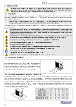
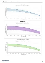
WARNING: Make sure that, when designing the pipe length and diameter, do not exceed the maximum head loss
on the plant side, please see the technical data given in the table of Paragraph 12 (available pressure head).
WARNING: Connect the pipes to the attacks by using always key against key system.
WARNING: The expansion vessel have a limited volume. The installator have to provide a further expansion vessel
if it is necessary.
WARNING: Unit water inlet pipe have to be in correspondence with the connection labelled: ”WATER INLET”,
otherwise the evaporator may freeze.
WARNING: It is compulsory to install on the WATER INLET connection a metallic filter (with a mesh not larger than
1mm) and a dirt separator. the warranty will no longer be valid If the water flow switch was manipulated or
altered or if the metallic filter and/or dirt separator were not installed. The filter and the dirt separator have to be
kept clean, therefore make sure that are clean after the unit installing the unit, and then check them periodically.
All units are standard supplied with the water flow switch (factory installed). The warranty will be invalidated if the
water flow switch was altered, removed, or if the water filter and the dirt separator were not installed on the unit.
Please refer to the wiring diagram for the water flow switch electric connections.
Make sur that the heating system and the safety valves must comply with the requirements of EN 12828.
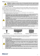
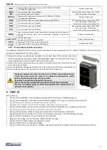
7.4.1
Drainage connection
All the units of MEX VS series have been designed to use their own base as a drain pan; a plastic pipe fitting is standard provided
to be installed onto the lower part of the unit in the special housing enabling the connection of a drainage pipe.
Each unit is also provided, on the basement of the hydronic kit (at the heat exchanger side), with a hole that can allow to drain any
condensed water can leach from plumbing pipes. As the pipes must be well-insulated, the production of condensed water is
however very low and therefore the connection of a drainage pipe to that hole is not very required.
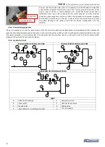
7.4.2
Plant circuit charging
WARNING: Verify all the charging/topping up operations.
WARNING: Before beginning the charging/topping up operation of the plant circuit, disconnect the unit for the
electric power supply.
WARNING: The charging/topping up of the plant circuit must always be done under controlled conditions of
pressure (max 1 bar). Make sure that you have installed on the line of charging/topping up a pressure
reducerdevice and a relief valve.
WARNING: The water on the charging/topping up pipe must be suitably pre-filtered from any impurities and
suspended particles. Make sure that you have installed a cartridge filter removable. Make sure that an extractable
cartridge filter and a dirt separator have been installed.
WARNING: It is required to proceed by air purging periodically in order to eliminate the accumulated air from the
plant circuit system.
WARNING: Make sure to install an automatic air vent valve at the highest point of the system.
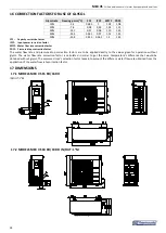
Drainage pipe fitting
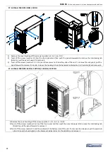
Drainage pipe fitting housing
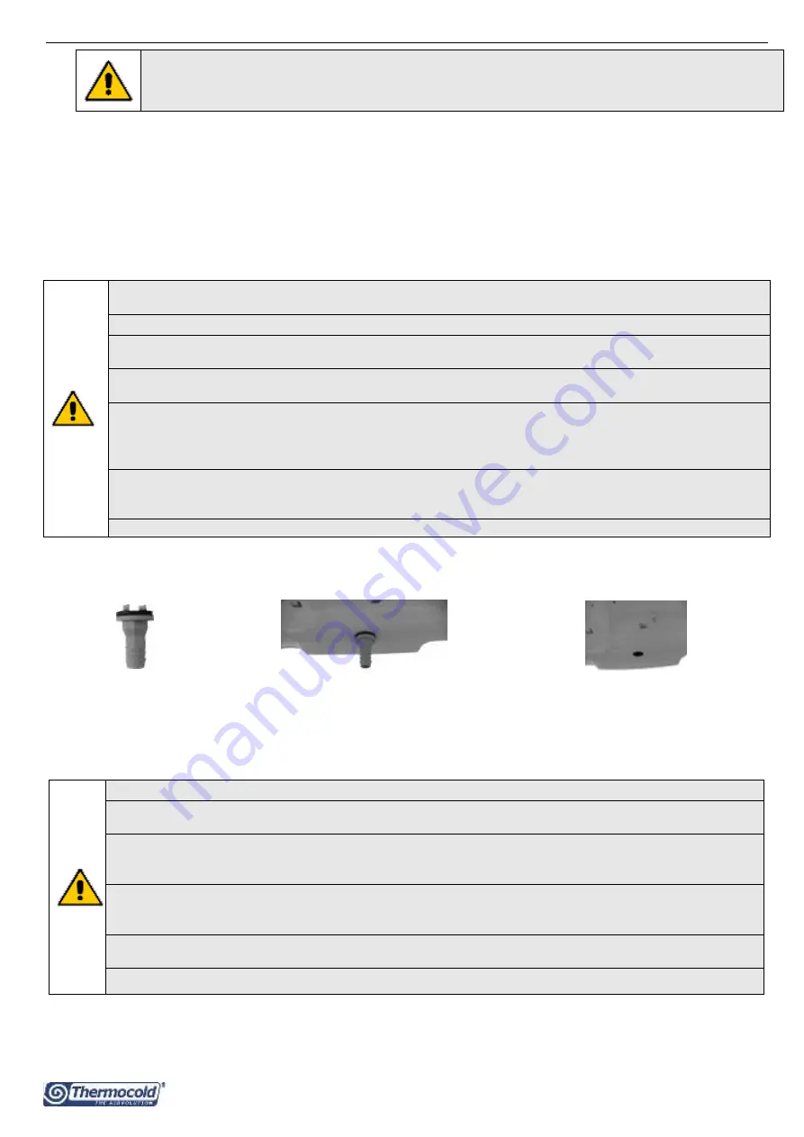
Drainage pipe fitting connected to the unit
Summary of Contents for MEX VS 112 RH
Page 39: ......


