background image


MULTIFUNCTIONAL UNITS RLC – Installation and maintenance manual 


MUMRLCHEAT_REV01_1012_UK


Pag. 26 di 31 


13


Start-Up Preliminary Procedures 

13.1


Preliminary check 

Before starting the unit, even only momentarily, all the machinery supplied by the chilled water, like the air handling units, pumps, etc. 

have  to  be  checked.  The  pump  auxiliary  contacts  and  the  flow  switch  have  to  be  connected  to  the  control  panel  as  indicated  in  the 
electrical diagram. Before carrying out interventions on the valve regulations, loosen the relevant valve gland. Open the discharge valve of 
the compressor. Open the liquid shutoff valve placed on the liquid line. Measure the suction pressure. If it is lower than 0.42 MPa jumper 
and strain the solenoid valve on the liquid line. Bring the suction  pressure to 0.45 MPa, then remove the jumper. Charge all the water 
circuit progressively. Starts up the water pump of the evaporator with the calibration valve shut and then slowly open it. 
Discharge the air from the high points of the water circuit and check the direction of the water flow. Carry out calibration of the flow by 
using a measurer (if present or available) or by means of a combination of the readings of the manometers and the thermometers. In the 
starting phase calibrate the valve on the pressure difference read on the manometers, carry out drainage of the tubes and then carry out 
fine calibration on the temperature difference between the water in and the water out. The regulation is calibrated in the factory for water 
in to the evaporator at 12°C and water out at 7°C. With the general switch open, check that the electrical connections are tightly clamped. 
Check for any possible refrigerant leaks. Check that the electrical data on the label correspond to those of the mains supply. Check that the 
thermal charge available is appropriate for starting. 

13.2


 Refrigerant seals control 

Thermocold units are sent with the complete charge of refrigerant and are at a sufficient pressure to check the seal after installing. If the 
system were not under pressure, blow refrigerants (vapour) into it until pressure is reached and look for leakage. 
After having eliminated the leakage, the system has to be dehydrated with a vacuum pump up to at least 1mm Hg - absolute pressure (1 
Torr o 133.3 Pa). This is the minimum recommended value to dehydrate the plant. 
Dangers do not use the compressor to vacuum the system. 

13.3


Refrigerant charge check 

Thermocold units are supplied with a complete charge of refrigerant. If bubbles can be seen through the peephole with the compressor 
running with a full charge and steadily, it means that the refrigerant charge is insufficient. 
Danger  While  refrigerant  is  being  added  do  not  exclude  any  control  system  and  let  the  water  circulate  in  the  evaporator  to  avoid  the 
formation of ice. 
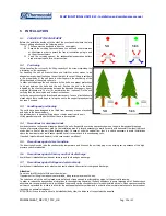
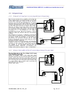
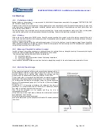
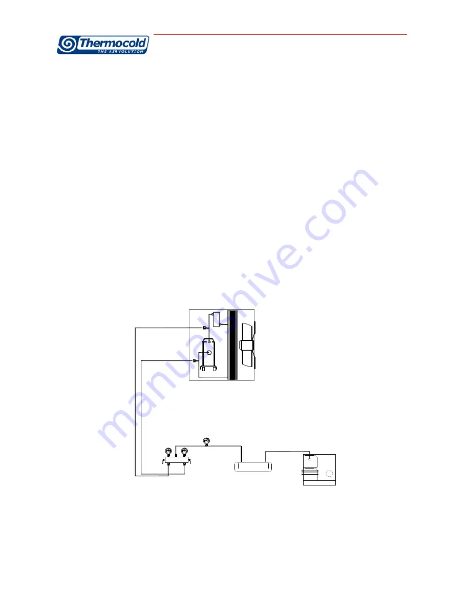
Cooling circuit diagram with connection to vacuum pump. 


manometro

alta pressione

bassa pressione

manometro

vacuometro

pompa del vuoto

trappola olio

presa bassa pressione

presa alta pressione

Summary of Contents for MULTIFUNCTIONAL UNITS RLC

Page 1: ...EV01_1012_UK Pag 1 di 31 MANUALE DI INSTALLAZIONE E MANUTENZIONE MULTIFUNZIONE RESIDENTIAL AND LIGHT COMMERCIAL INSTALLATION AND MAINTENANCE MANUAL FOR MULTIFUNCTIONAL UNITS RESIDENTIAL AND LIGHT COMM...

Page 2: ...g a Thermocold product Thermocold operates in civil and industrial air conditioning for years to assure the best comfort with reliability quality efficiency and total safety With this manual we try to...

Page 3: ...al Connections 14 8 Water Connections 15 9 Perdite di carico sugli scambiatori 24 10 Tabelle di correzione glicole etilenico Errore Il segnalibro non definito 11 Tabelle di correzione fattore di incro...

Page 4: ...he electrical panel F Warranty is automatically over in case of payments not fulfilled non performance of the contract and even if the units show tampering without THERMOCOLD writing approvals G Non o...

Page 5: ...stic of the unit and the installed components Without this code it is not possible identifies the specific spare parts of the unit In case of request for repair it is necessary the model and the seria...

Page 6: ...ous operations that could damage the unit Make sure that the unit has the proper positioning during transportation Placing horizontally the unit can lead to irreversible damage to the compressors Faul...

Page 7: ...t esterna va ancorata su antivibranti in gomma o a molla che vanno fissati nel seguente modo Firmly fasten the anti vibration bottom part to the support base plate of the unit Screw the fastening nut...

Page 8: ...equipped with coil protection grilles is completely accessible with danger for cuts and abrasions In these cases technicians and operators must be aware about this risk For all the units which allow...

Page 9: ...naesthetic effects up to a loss of conscience Long exposures could give rise to cardiac arrhythmia and sometimes even to death High concentrations can create a reduction of oxygen in air with conseque...

Page 10: ...aring the right protections In case of accidental contact with refrigerant due to the safety valves exhaust it is necessary to follow the above indicated 2 5 carry out the plant connections to the uni...

Page 11: ...e switch on the side of the panel and only after having placed a sign which says do not use maintenance in progress if modifications must be carried out to the cooling hydraulic or electrical circuit...

Page 12: ...ided with the unit have to be respected 5 4 Precautions for dominant winds Avoid obstacles on suction and discharge sides of the units Respect the servicing spaces as shown on the units dimensional dr...

Page 13: ...e linear meter nd inch W mt 8 1 4 5 10 3 8 5 15 1 2 5 20 3 4 10 25 1 13 40 1 1 2 30 50 2 50 65 2 1 2 80 80 3 120 100 4 200 125 5 300 150 6 450 200 8 750 Electrically unconnected unit in this case the...

Page 14: ...th a three core cable of a section which is appropriate to the machine absorption The switch and the fuses like all the power connections must comply with the regulations in force 7 3 Unbalance betwee...

Page 15: ...ssors See the chapter on the thecnical data The declared content can be reduced by the amount contained in the distribution piping system only for the air conditioning system Undersized tanks reduce t...

Page 16: ...follow the effective plant demand Place the outlet water probes to 1 mt minimum distance from the check valves located downstream of the exchanger Before a machine stop with temperatures close to 0 C...

Page 17: ...AL PUMP T M DEHUMIDIFIER DEUMUDIFICATORE M T EWR REC PRS PRS VALVOLA PRESSOSTATICA PRESSURE REGULATOR For units with geothermal source a system for regulating the condensation or evaporation pressure...

Page 18: ...the secondary In this case the circulator of such a ring is on customer charge Otherwise you can select the pump from the Thermocold tank catalogue T T TEMPERATURE PROBE SONDA DI TEMPERATURA T SF VAL...

Page 19: ...mperatura aria esterna C temperatura di produzione acqua C Summer air conditioning and simultaneuosly hsw production operating mode Summer air conditioning operating mode 15 20 25 30 35 40 45 50 20 15...

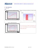
Page 20: ...ace heating and hsw production operating mode Summer air conditioning and simultaneuosly hsw production operating mode Summer air conditioning operating mode Notes working outside of the allowed limit...

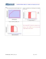
Page 21: ...ce heating and hsw production operating mode Summer air conditioning and simultaneuosly hsw production operating mode Summer air conditioning operating mode Notes working outside of the allowed limits...

Page 22: ...inter space heating and hsw production operating mode Summer air conditioning and simultaneuosly hsw production operating mode Summer air conditioning operating mode Notes working outside of the allow...

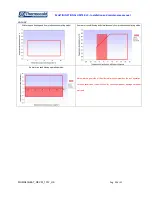
Page 23: ...ace heating and hsw production operating mode Summer air conditioning and simultaneuosly hsw production operating mode Summer air conditioning operating mode Notes working outside of the allowed limit...

Page 24: ...erent from the nominal one and so with temperature deviation different frm the nominal one It is not recommended that the unit works with very high temperature deviation because very low water flow ra...

Page 25: ...1 11 Ethylenic glycol correction table In order to calculate performance with glycolic solutions multiply main sizes by respective coefficients 12 Scaling correction table for packaged versions In ord...

Page 26: ...perature difference between the water in and the water out The regulation is calibrated in the factory for water in to the evaporator at 12 C and water out at 7 C With the general switch open check th...

Page 27: ...line downstream of the thermostatic valve bulb read the balance pressure to the evaporator on the low pressure manometer and the corresponding saturation temperature Overheating is equal to the differ...

Page 28: ...r In order to keep all the machine components in good condition and to optimise their use during the warm up it is necessary to bring the circuit to the right temperature before releasing cooling ener...

Page 29: ...ts to protect Description of the operations Recommen ded frequency Control of compressor oil level monthly Control of the suction temperature superheating monthly Control of the hydraulic circuit wate...

Page 30: ...1 per type fans and engines 1 per type electrical components all compressors 1 per type 5 year Components Quantity fuses all filter dryers all solenoid valves all thermostatic valves all pressostats...

Page 31: ...export thermocold it marketing thermocold it Le informazioni tecniche contenute nel presente manuale non sono impegnative La Thermocold Costruzioni S r l si riserva la facolt di apportare in qualsias...

Reviews: