1-2
Figure 1-1
Fiber-Optic Probe Tip
D
ISTANCE
C
ONTROL
M
ECHANISMS
Tip geometry alone is not enough to produce images. The tip must also be very close to the
sample, typically <10 nm. These small separations are only possible with electronic
position detection and control. Distance control is currently achieved using a shear-force
mechanism. Two such mechanisms exist: light-lever and tuning fork. For these tech-
niques, the tip is attached to a vibrating element which is driven at its resonant frequency.
This vibration is parallel to the surface. As the tip approaches the surface, the vibration
amplitude and phase change. This change in amplitude and phase generates an electrical
signal that is input into the feedback loop.
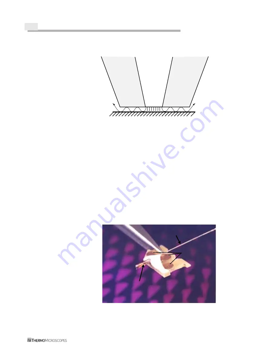
The Aurora-2 uses the tuning fork mechanism for distance control, as it has the advantage
of producing an electrical signal directly, rather than relying on another device to generate
a signal. This direct connection provides better feedback control, uses much smaller
vibration amplitudes, and does not introduce unwanted light into the sample area.
Figure 1-2
Aurora-2 Fiber-Optic Probe
Sample Surface
Fiber
Aluminum
coating
Aluminum
coating
100nm
50nm
Tuning fork
Contacts
Fiber
Summary of Contents for Aurora-2
Page 30: ...2 18 Figure 2 20 Reflection Tower Controls Swivel Tilt Focus Rotating mirror selector ...
Page 44: ...3 8 ...
Page 52: ...5 4 ...
Page 54: ......


