2-14
Step 6
Raise the thumbscrews located on the front of the head by turning them clockwise
one full turn. This will keep the tip from hitting the stage when the head is placed
on the stage.
Step 7
Carefully place the head on the stage, and plug the data cable into the head, as
described above on page 2-10.
Step 8
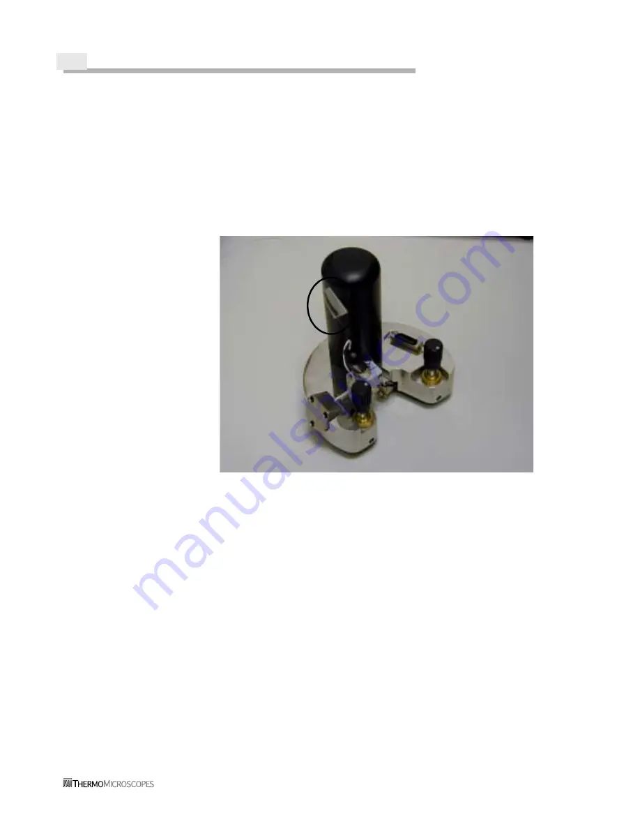
Tape the fiber to the Z motor enclosure on the head, as shown in Figure 2-15. This
takes strain off the fiber and helps prevent separation from the probe.
.
Figure 2-15
Fiber Taped to the Aurora-2 Head
Step 9
Use the fiber stripper tool to strip away about 25mm of the polymer buffer off the
end of the tip fiber. Note that once stripped, the fiber is very brittle.
Step 10
Use the optical fiber cleaver from the tool kit to cleave the end of the tip fiber:
(a)
Open the jaws of the cleaver, and seat the fiber into the notch in the lower jaw.
(b)
Insert the fiber until the stripped portion on the end aligns with the 16 mm mark.
(c)
Press the scoring bar down on the fiber. Take care not to break the fiber.
(d)
Gently flex the tongue of the cleaver down until the fiber cleaves. Take care not
to touch the tip.
Step 11
Carefully insert the fiber into one end of the cam splicer. Gently roll or twist the
fiber as it is inserted to help it enter. Insert about 15mm into the splicer. Leave
the coupler open, with the lock arms up.
Step 12
Gently seat the fiber into the fiber holder on the end of the cam splicer assembly.
Summary of Contents for Aurora-2
Page 30: ...2 18 Figure 2 20 Reflection Tower Controls Swivel Tilt Focus Rotating mirror selector ...
Page 44: ...3 8 ...
Page 52: ...5 4 ...
Page 54: ......


