T
AKING
A
T
OPOGRAPHIC
I
MAGE
3-3
Aurora-2 User’s Manual
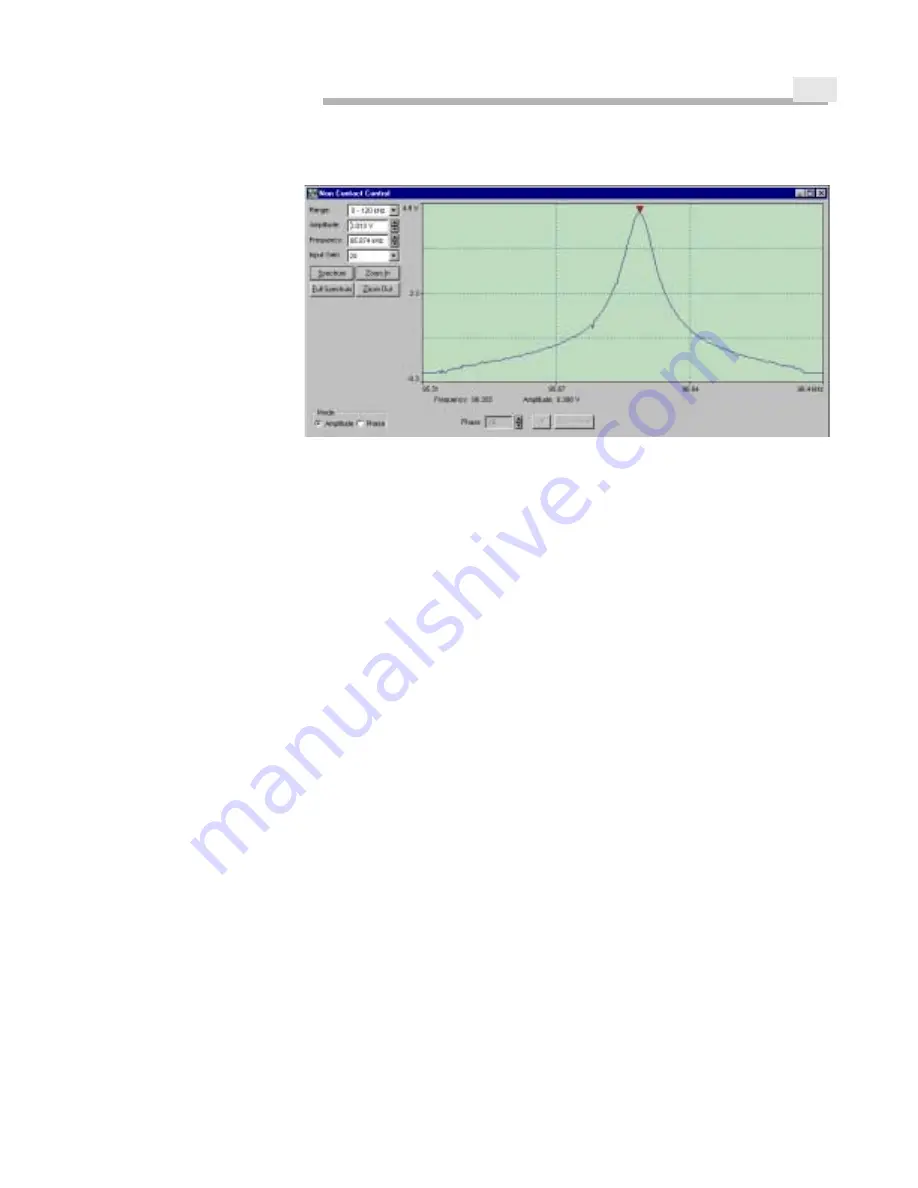
Figure 3-1
Selecting the Drive Frequency
Step 10
Select P
HASE
from the Mode group box in the Non Contact window, and watch
the internal sensor signal.
Step 11
Click on the A
UTO
P
HASE
button in the Non Contact window. The internal sensor
signal should go to 0.
Step 12
Click on the +90 button three times (for a total of 270 degrees) to find the phase
that shows the most negative value for the internal sensor signal.
Step 13
Fine tune the Non Contact controls using the following guidelines:
The aim to have the drive amplitude be as low as possible while keeping the
internal sensor signal at approximately the same value and the RMS noise (dis-
played in blue in the Signal window) less than 0.1.
Reducing the drive amplitude will cause the internal sensor signal to increase
(move closer to 0). Increasing the gain will bring the internal sensor signal down
(more negative, i.e., further from 0). However, increasing the gain will propor-
tionally increase the RMS noise.
Step 14
Once the Non Contact controls have been fine-tuned, minimize the Non Contact
window. To adjust these settings, the tip must be out of feedback. These settings
will be saved when you exit the SPMLab software.
M
OVING
THE
T
IP
INTO
F
EEDBACK
Step 1
Set the rotating mirror to reflection mode.
Step 2
Use the thumbscrews to lower the head. Bring the tip within a few millimeters of
the surface.
Step 3
Lower the set point below the current sensor signal level. For example, if the
sensor signal level is -30 nA, lower the setpoint to -50 or -60 nA.
Step 4
Select “Z-Piezo” from the drop down signal list to the right of the lower
oscilloscope to monitor the z-piezo voltage.
Summary of Contents for Aurora-2
Page 30: ...2 18 Figure 2 20 Reflection Tower Controls Swivel Tilt Focus Rotating mirror selector ...
Page 44: ...3 8 ...
Page 52: ...5 4 ...
Page 54: ......


