INSTALLATION PROCEDURES
3
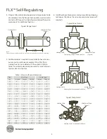
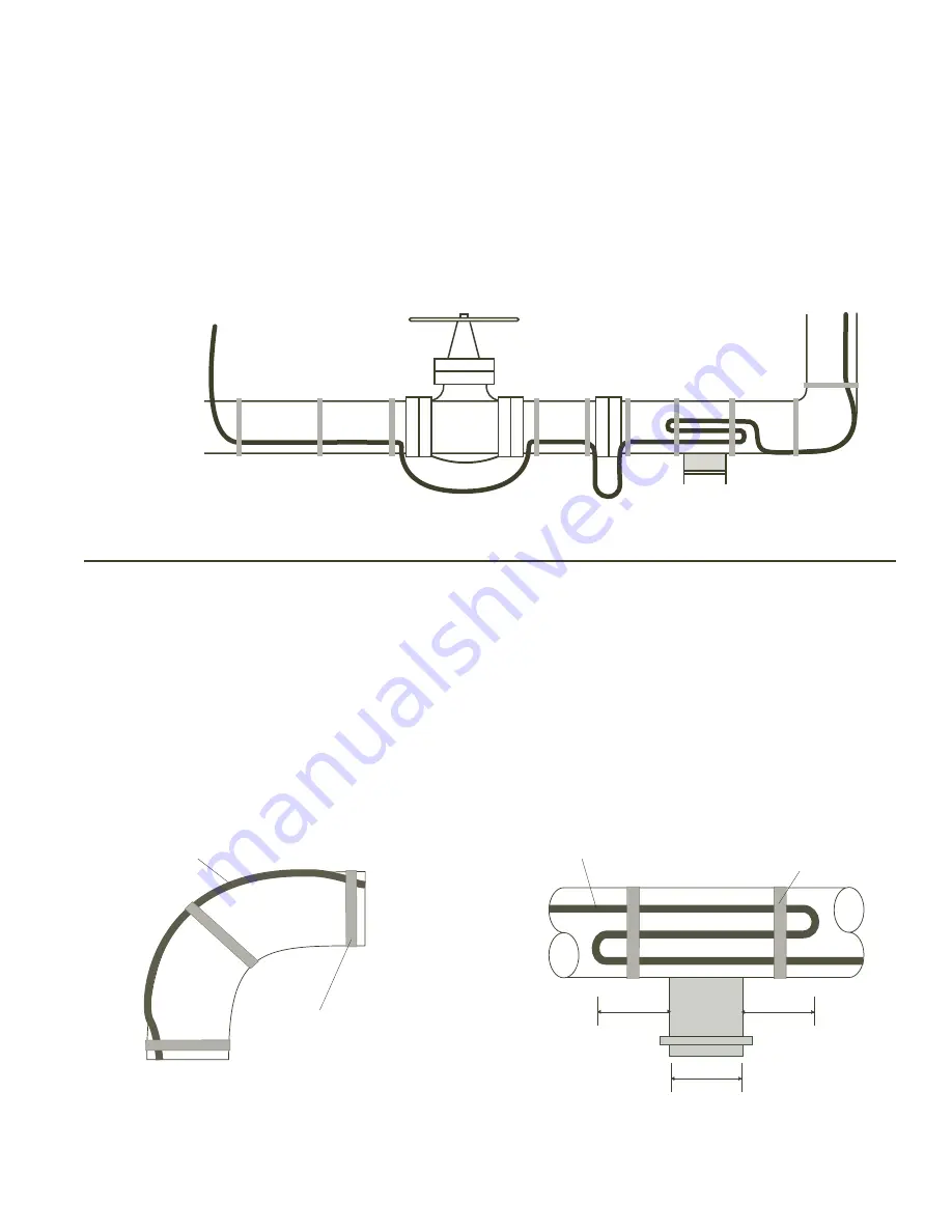
2. Make heating cable allowances for valves, flanges, elbows
and supports as per the applicable drawings and table on
pages 2 and 3 of these installation procedures. See product
specifications sheet for heating cable minimum bend radius.
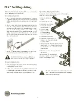
Temporary Installation
Proposed End-of-Circuit
Location
Proposed Power
Connection Location
Pipe Support
Cable Allowance for
In-Line Heat Sinks
Initial Installation . . .
1. Begin temporary installation at the proposed end-of-circuit
location and lay out heating circuit on the pipe, allowing ex-
tra cable for the power connection and for any splice loca-
tions. Refer to illustration below for temporary installation.
Installation on Fittings and Equipment . . .
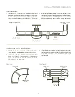
1. Install heating cable in accordance with illustrations below.
Secure heating cable to piping using attachment tape.
2. Elbows: Locate the cable on the outside radius of an elbow
to provide sufficient heat to compensate for the added pip-
ing material. Secure the cable to the pipe on each side of
the elbow with attachment tape.
Attachment Tape
(Typical)
Heating Cable
Pipe Elbow
Pipe Support
Support
Length
Attachment Tape
(Typical)
Heating Cable
3” Min.
(8 cm)
3” Min.
(8 cm)
3. Pipe Supports: Insulated pipe supports require no additional
heating cable. For uninsulated supports, allow two times the
length of the pipe support plus an additional 15” (40 cm) of
heating cable.


