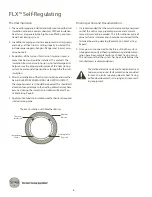
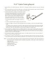
background image

FLX


™ Cable Testing Report

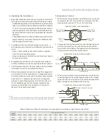
1.  Refer to Thermon FLX Installation Procedures, FORM CPD1018, for general installation procedures, requirements and guide-

lines.

2.  Upon receiving heating cable, check the cable to make sure the proper type and output have been received. All cables are 

printed on the outer jacket with part number, voltage rating and watt output.

3.  Visually inspect cable for any damage incurred during shipment. 

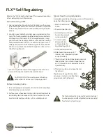
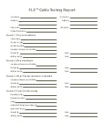
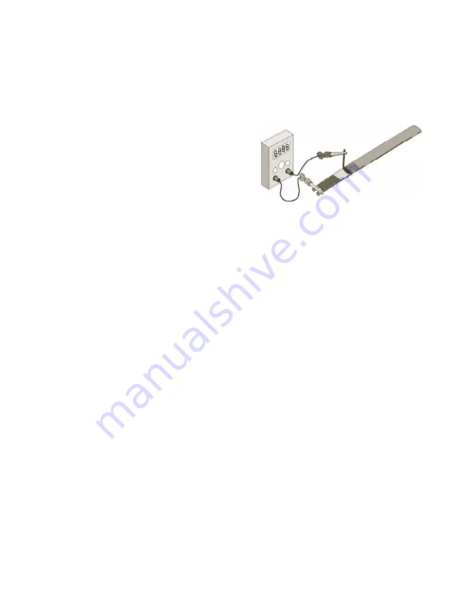
The heating cable should be tested to ensure electrical integrity 
with at least a 500 Vdc megohmmeter (megger) between the 
heating cable bus wires and the heating cable metallic braid.  
IEEE 515.1 recommends that the test voltage for polymer  
insulated heating cables be 2500 Vdc. Minimum resistance  
should be 20 megohms. (Record 1 on Cable Testing Report.)

A.  Connect the positive lead of the megger to the cable bus 

wires.

B.  Connect the negative lead of the megger to the metallic braid.

C.  Energize the megger and record the reading. Readings between 20 megohms and infinity are acceptable. Readings 

below  
20 megohms may mean the electrical insulation has been damaged. Recheck the heating cable for physical damage 
between the braid and the heating element; small cuts or scuffmarks on the outer jacket will not affect the megger 
reading unless there was actual penetration through the braid and dielectric insulation jacket.

4.  Once the installation is complete, but prior to installation of thermal insulation, recheck the heating cable with at least a 

500 Vdc megohmmeter (megger) between the heating cable bus wires and the heating cable metallic braid. IEEE 515.1 
recommends that the test voltage for polymer insulated heating cables be 2500 Vdc. Minimum resistance should be 20 
megohms.  (Record 2 on Cable Testing Report.)

5.  After the thermal insulation is installed, the megohmmeter test should be repeated. Minimum resistance should be 20 

megohms.  (Record 3 on Cable Testing Report.)

6.  After the thermal insulation is installed and power supply is completed, record the panel and circuit breaker information. 

Ensure all junction boxes, temperature controllers, cable glands, etc. are properly secured.  Set the temperature controller 

NOTE:  To ensure the heating cable warranty is maintained through installation, the testing outlined on 

this sheet must be completed on the installed heating cables, and the test results recorded and 

mailed/faxed to:


Thermon Customer Service 

100 Thermon Drive 

San Marcos, Texas 78666 

Fax: 512-754-2420 


7

Summary of Contents for FLX Self-Regulating

Page 1: ...FLXTM Self Regulating Winterization Freeze Protection INSTALLATION PROCEDURES ...

Page 2: ... Remove dirt rust and scale with a wire brush and oil and grease films with a suitable solvent Refer to the FLX Cable Testing Report for required recording of test data and circuit information Upon Receiving Cable 1 Uponreceivingheatingcable checktomakesuretheproper type and output have been received All cables are printed ontheouterjacketwithpartnumber voltageratingandwatt output 2 Visually inspe...

Page 3: ... and for any splice loca tions Refer to illustration below for temporary installation Installation on Fittings and Equipment 1 Install heating cable in accordance with illustrations below Secure heating cable to piping using attachment tape 2 Elbows Locate the cable on the outside radius of an elbow to provide sufficient heat to compensate for the added pip ing material Secure the cable to the pip...

Page 4: ...le Attachment Tape Typical Pipe Size Valve Type Screwed Flanged Welded Pump Type Screwed Flanged 6 1 0 1 2 9 1 6 0 1 6 3 1 1 2 1 2 4 1 1 6 2 1 3 4 6 1 1 6 2 6 1 6 3 5 2 2 2 6 2 4 5 6 3 2 6 3 6 2 6 5 7 4 4 5 3 8 10 6 7 8 3 6 14 16 8 9 6 11 4 19 22 10 12 6 14 4 25 28 12 15 16 6 5 30 33 14 18 19 6 5 6 36 39 16 21 6 23 6 43 46 18 25 6 27 6 6 51 54 20 28 6 30 7 57 60 24 34 36 8 68 72 30 40 42 10 80 84 ...

Page 5: ...dc The mini mum acceptable level for the megger reading for any polymer insulated heat tracing cable is 20 megohms Record 2 on Cable Testing Report Heating Cable vs Sensor Location Temperature Control 1 Whenalinesensingcontrollerisspecified thesensorshould be placed at least 90 around the circumference from the heating cable or at least 2 5 cm from the cable Tape Length Pipe Diameter in Inches 1 1...

Page 6: ...n cannot be overemphasized Without insulation heat losses are generally too high to be offset by a conven tional heat tracing system 2 In addition to piping and in line equipment such as pumps and valves all heat sinks must be properly insulated This includes pipe supports hangers flanges and in most cases valve bonnets 3 Regardless of the type or thickness of insulation used a protective barrier ...

Page 7: ...al damage between the braid and the heating element small cuts or scuffmarks on the outer jacket will not affect the megger reading unless there was actual penetration through the braid and dielectric insulation jacket 4 Once the installation is complete but prior to installation of thermal insulation recheck the heating cable with at least a 500 Vdc megohmmeter megger between the heating cable bu...

Page 8: ...Date Witnessed By Date Record 2 After Installation Insulation Resistance M Ohms Tested By Date Witnessed By Date Record 3 After Thermal Insulation is Installed Insulation Resistance M Ohms Tested By Date Witnessed By Date Record 4 Final Commissioning Panel Number Breaker Number Volts Ambient Temperature deg F Recorded Amps Tested By Date Witnessed By Date FLX Cable Testing Report ...

Page 9: ... 396 5801 Facsimile 512 396 3627 800 820 HEAT www thermon com In Canada call 800 563 8461 Other Products Thermonoffersadditionalcut to lengthcablesor complete turn key systems for the following applications Hot Water Temperature Maintenance Freezer Floor Frost Heave Prevention Tank and Hopper Heating Instrument Tubing Bundles Control and Monitoring Systems ...

Reviews: