

3
The Terminator ZP/FAK-1 Split Bulkhead Entry Kit is designed to
make a waterproof seal over the end of TubeTrace and terminate
Thermon electric heat trace in an approved junction box. Review
Instructions prior to installation. Kit will make one connection.
INSTALLATION PROCEDURES
Installation Precautions
• To minimize the potential for arcing on electrical heat tracing
and fire caused by product damage or improper installation,
use ground-fault protection.
• Installation must comply with Thermon requirements and be
installed in accordance with any applicable national and local
codes.
• Component approvals and performance ratings are based on
the use of Thermon specified parts only. User supplied power
connection fittings must be listed or certified for intended use.
• De-energize all power sources before opening enclosure.
• Keep ends of bundles, heat tracing and kit components dry
before and during installation.
• Individuals installing these products are responsible for
complying with all applicable safety and health guidelines.
Proper personal protective equipment, or PPE, should be
utilized during installation. Contact Thermon if you have any
additional questions.
Terminator ZP Certifications/Approvals
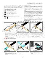
2.
Trim heat tracing to within 305 mm–381 mm
(12”–15”) of the end of the insulation. If
self regulating heat trace proceed to step
3. For Zone-type heat trace continue with
indentification of bus connection on step 2a.
1.
Remove outer jacket and insulation from tubing
bundle as included from end of the tubing
bundle. Ensure sufficient heat trace is available
for electrical connection. See instructions
included with heat trace PETK kit (purchased
separately).
2a.
Strip back bundle insulation 38 mm (1-1/2”)
to 76 mm (3”) beyond bus connection
heat
tracing. If bus connection indentation is less
than 305 mm–381 mm (12”–15”) from end of
the heat tracing, proceed stripping the bundle
insulation to the next indentation.
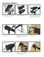
3.
Wrap tubes and heat tracing with pass of heat
reflective tape (25% overlap). Then wrap with 3
passes of glass fiber tape (50% overlap), or until
fiber tape is equal to original bundle insulation
thickness.
4.
Complete with additional passes of heat
reflective tape.
Trim as Required
for Connection
Tubing Bundle
Tubing
Heat Tracing
Tubing
Self-Regulating Heat Tracing
Heat Tracing
305 mm–381 mm
(12”–15”)
Insulation
Zone Type Heat Tracing
Tubing
Bus Connection
Indentations
(Zone Heater Only)
305 mm–381 mm
(12”–15”)
Insulation
Glass Fiber Tape
Heat Reflective Tape
Heat Tracing
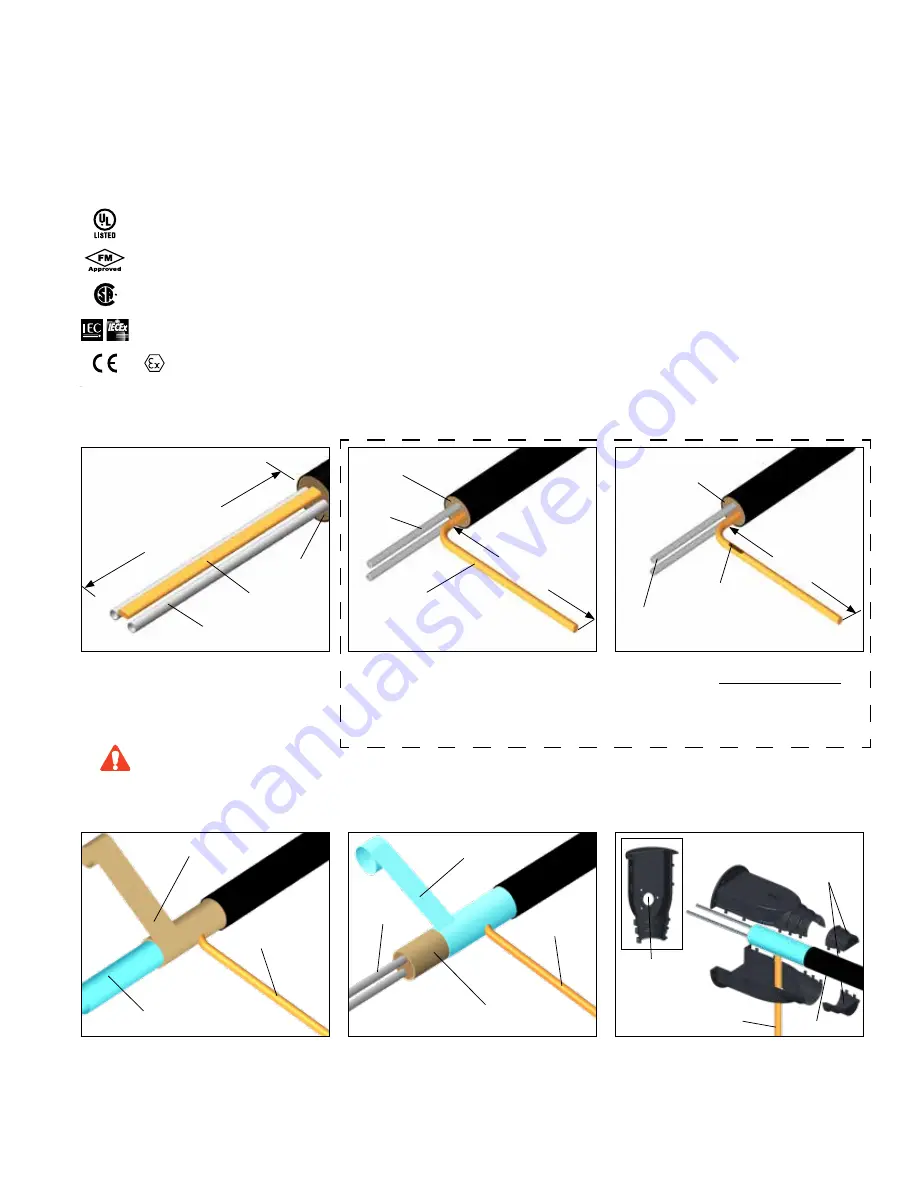
5.
Cut FAK-1 top and base ends to match outside
diameter of tubing bundle and remove end
pieces.
Heat Reflective Tape
Glass Fiber Tape
Heat Tracing
Tubing
CAUTION
(Found on TubeTrace SE/ME bundles)
Do not cut or damage the heat
trace or sampling tube.
Tubing Bundle
Cut and Remove
to fit
Heat Tracing
Field Drilled
(By Others)
IP66/Type 4X -60°C ≤ Ta ≤ +55°C
Listed Heat Tracing Cable System 137M
Ordinary & Hazardous Locations
Class I, Division 2, Groups A, B, C, & D
Class II, Division 2, Groups F & G, Class III
Class I, Zone 1, AEx eb IIC T4-T6
09.2238691,-G,-S, Ex e IIC T4-T6
FMG 10.0022X Ex eb IIC T4-T6, Ex tb IIIC T135°C-T85°C
1725 II 2 GD Ex eb IIC T4-T6, Ex tb IIIC T135°C-T85°C FM 10ATEX0058X


