

4
Terminator ZP/FAK-1
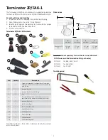
6.
Mount expediter base with o-ring to FAK-1
base using (3) M5 mounting screws and lock
washers. Punch out weep hole.
O-Ring
Expediter
Base
Mount Screw
and Washers
Weep Hole
FAK-1 Base
Silicone
Gasket
7.
Install RTV silicone and gasket, cutting off excess.
Apply RTV sealant to both halves.
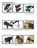
Drilled hole
for bundle
entry
Drilled holes
for securing
FAK-1
Drilled holes for
securing FAK-1
Use as template
11.
Field drill required entry hole in wall/plate. Use
the FAK-1 flange as a template and mark and
drill holes for bolts.
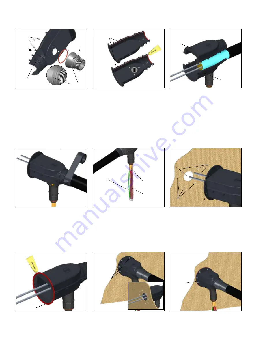
9.
Apply self-vulcanizing tape around bundle jacket
and work up over FAK ends.
FAK-1
Bottom Cover
FAK-1
Top Cover
RTV Sealant
12.
Apply RTV bead to back of FAK-1 flange prior
to securing to bulkhead.
RTV Bead
Backside View
Stainless Steel Bolts
14.
Apply RTV bead around FAK-1 flange.
13.
Secure FAK-1 to bulkhead/wall using (8) eight
stainless steel bolts. Note: s
tainless steel
bolts, washers, and nuts provided by others.
Recommended bolt size is 8-32.
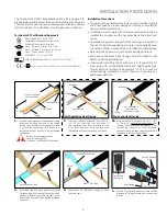
8.
Assemble FAK-1 top, tubing bundle, and FAK-1
bottom together as shown Snap together firmly.
Inspect ends of tubing splice cover for snug fit.
Apply additional RTV sealant where needed.
10.
Terminate heat tracing with appropriate PETK
termination kit. Refer to PETK installation
instructions (purchase separately) for details
not addressed here.
Power Connection
Boot
Heat Tracing
Ground Braid


