
Thermon • 100 Thermon Dr • PO Box 609 San Marcos, TX 78667-0609 • Phone: 512-396-5801 • 1-800-820-4328
For the Thermon office nearest you visit us at . . . www.thermon.com
© Thermon, Inc. • Printed in U.S.A. • Information subject to change.
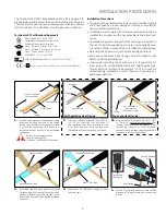
Typical Wiring Diagram.
L 2 or N
L 1
Power Supply
Ground
Power Cable
Heat Trace
Ground Braid
Form 50079-0219
INSTALLATION PROCEDURES
15.
For power connection applications: Use
dimple molded into side of junction box base
to locate center hole, drill for user supplied
power connection fitting per manufacturer’s
recommendations.
16.
Mount junction box on expediter making sure
to align slots to properly orient junction box
base.
Align Slots
Dimple for
Center Line
Drilled thru (1) Wall
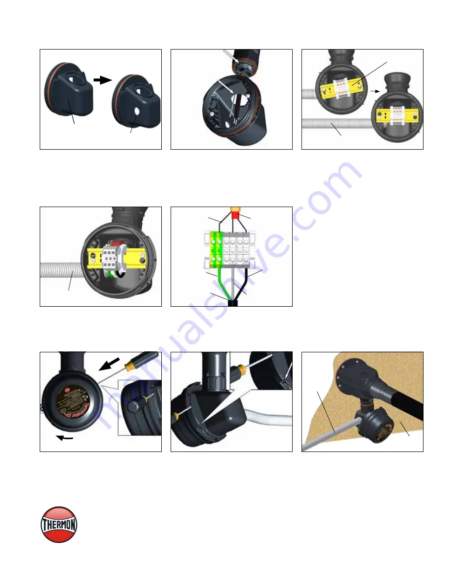
21
. Completed Terminator ZP/FAK-1 for bulkhead
entry of electrically heated TubeTrace bundles.
Power
Connection
Bulkhead
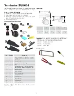
17.
Install quick mount terminal blocks twist to
position and tighten screws. (By others for
power connection application.)
Terminal Blocks
(Typical)
18.
Complete system wiring between fabricated
heat tracing and power supply wiring. See
wiring diagram.
Power Wiring &
Conduit By Others
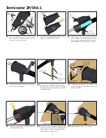
19.
Install junction box lid and twist hand tight.
Insert screwdriver into ratchet slot located
on side of junction box base to tighten. Use
screwdriver ratchet on junction box lid. Lid will
rotate 30°.
30°
20.
Lid latch mechanism fully engaged. To remove
lid, repeat step 15 but in opposite direction.
Conduit and Wire (By Others
For Power Connection Applications)