Page 7
1.
The wire coloured green and yellow
must be connected to the
terminal in the plug which is marked by the letter E, or by the
safety earth symbol coloured green, or green and yellow.
2.
The wire coloured blue
must be connected to the terminal which
is marked with the letter N, (Neutral connector)
3.
The wire coloured brown
must be connected to the terminal
which is marked with the letter L, (Live connector)
4.
NOTE:
Replacement of the mains cable
must be done by a competent
service engineer.
HEATING ELEMENT
The heating element
fitted to this press is rated at 500 Watts.
Never connect
to any outlet or power supply having a different
voltage/frequency from that on the machine data plate.
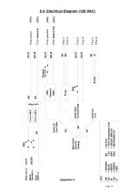
2.3B Wiring the plug for a 120 VAC machine.
1.The wire
which has green insulation must be connected to the
terminal in the plug coloured green or marked GR.
2.The wire
which has white insulation must be connected to the
terminal in the plug identified as neutral.
3.The wire
which has black insulation must be connected to the
terminal in the plug which is identified as live (line).
4. Note:
Replacement of the power cord must be carried out by a
qualified electrician in accordance with national and local electrical
codes, and the instructions provided with the plug.
2.4
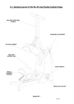
Adjusting the pressure
This press is fitted
with a pressure adjusting unit, which enables the heat
plate assembly to be raised or lowered by use of a pressure adjustment knob
located on the top of the machine:
a)
To increase pressure
or to use thinner materials turn knob
clockwise.
b)
To decrease pressure
or to raise the heat plate assembly to enable
thicker materials to be used, turn the adjustment knob
anticlockwise.
NOTE
DO NOT adjust the pressure when the machine is clamped shut
CAUTION
Never increase the pressure to the extent of requiring undue force to
lower the toggle/heat plate assembly into the lock position, as this will
place excessive stress on the press frame, resulting in permanent
damage to the press.
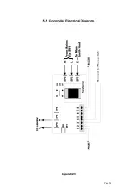
2.5 Adjusting the time and temperature
Please refer to Appendix II showing the operation of the control
unit.
Summary of Contents for Almere NL-22
Page 1: ...NL 22 Combo Heat seal machine ...
Page 18: ...Page 14 ...
Page 19: ...Page 15 ...
Page 20: ...Page 16 ...
Page 21: ...Page 17 ...
Page 22: ...Page 18 ...
Page 23: ...Page 19 ...
Page 24: ...Page 20 ...
Page 25: ...Page 21 ...


