background image

8

BACK TO INDEX

For more information about our products and how to contact us, please visit thermopatch.com

Sealing Pressure:
A label to indicate the direction in which to turn the Lower Press Platen is mounted directly below the 

Lower Press Platen. To increase inter-platen pressure, turn the Lower Press Platen counterclockwise. 

To decrease the inter-platen pressure, turn the Lower Press Platen clockwise. The Pressure Settings in 

the Heat Sealing Guide on page 2-3 are obtained as follows:

1.   Turn the Lower Press Platen clockwise until it has bottomed out 

against the machine base.

2.   Turn the Lower Press Platen counterclockwise until the first 

“click” is detected. This Pressure Setting is zero pressure.

3.   To set the Lower Press Platen to a selected Pressure Setting, 

count the number of “clicks” turning the Lower Press Platen 

counterclockwise, increasing pressure.

4.   To set the Lower Press Platen to a new selected Pressure Setting from and existing setting, count 

the number of “clicks” from the existing setting, turning the Lower Press Platen clockwise or 

counterclockwise.  

Settings may vary depending upon garment thickness. Normally, higher pressures will produce more 

effective heat seals. However, the use of excess pressure may force adhesive through the fabric, 

with an undesired result.

Difficuly in locking the Seal Arm Handle of the HS-4-C machine in a closed position is anindication of too 

much inter-platen pressure. To prevent excess pressure when sealing thick garments, screw the Lower 

Press Platen all the way down. A Lower Press Platen that is worn from use can cause insufficient inter-

platen pressure. 

The Lower Press Platen should be replaced with Lower Press Platen SPA43941. When the pressure is too 

high, preventing the machine to open by itself, this has to be done manually. After this, switch off the 

machine for 5 seconds and switch it on again, resetting the machine.

CAUTION! 

Use of excess pressure can cause the HS-4-C machines to become locked in a closed position 

and difficult to open. Extreme pressure may severly damage the machine.

Summary of Contents for HS-4-C

Page 1: ...EN U S E R M A N U A L HS 4 C v 2 2 01 22...

Page 2: ...tion Dear user Congratulations and welcome to the ever growing number of Thermopatch users You have acquired a machine which has been manufactured by Thermopatch with the greatest possible care We are...

Page 3: ...tions of warranty and product liability 5 2 Installation 6 2 1 Instruction for handling 6 2 2 Installing and connecting the HS 4 C 6 3 Operating the HS 4 C 7 3 1 Starting up 7 3 2 Functionality 7 4 Ma...

Page 4: ...ch com to find your supplier E mail sales thermopatch nl 1 4 Specifications of the HS 4 C The machine HS 4 C is practical and universally applicable It can be used to apply patches textile emblems hea...

Page 5: ...that we state underneath a few pointers which will limit existing risks to a minimum Unplug the machine from the wall socket whenever you are maintaining or cleaning the machine Make sure there is en...

Page 6: ...er point we advise you to pack the machine in a similar fashion Let the machine cool down completely before packing and moving it 2 2 Installing and connecting the HS 4 C Take the Thermoseal HS 4 C fr...

Page 7: ...the machine is active during a Sealing Cycle LCD Display Functions The following describes the LCD Display functions and displays The Celsius or Fahrenheit LED will light up continuously once the tem...

Page 8: ...ing from and existing setting count the number of clicks from the existing setting turning the Lower Press Platen clockwise or counterclockwise Settings may vary depending upon garment thickness Norma...

Page 9: ...ur Thermopatch supplier Sealing pad Clean the sealing pad while it is still warm Use a clean lint free cloth to clean it regularly Do not heat seal on zippers staples buttons etc to avoid damage by pu...

Page 10: ...nstallation to check See I Introduction Replace Replace Return circuit board to factory for repairs Time malfunction Loose wires Timer is defective Micro switch is defective Check Return circuit board...

Page 11: ...sor broken Error 3 Error in Eprom the processor has no access to the memory for saving or reading of information Error 4 HS 4 C only Motor timed out not in position or motor switch error The correct p...

Page 12: ...ng pad SPA43941 Teflon cover self adhesive SPA9000 Fuse 2x 20015 26 3 15 A Fuse 6 2 Parts identification and location of components by name Power Entry Module Item Description QTY Part Number 1 Electr...

Page 13: ...how to contact us please visit thermopatch com Controller Board Item Description QTY Part Number 5 Electrical Chassis 1 46326 6 4 40unc x Socket Hex Cap Screw 4 21063 02 C 7 4 Spring Lockwasher 4 210...

Page 14: ...ement Item Description QTY Part Number 9 20unc x 5 8 Socket Hex Cap Screw 1 21063 05 K 10 M5 Hex Nut 4 21045 07 A 11 M5 Spring Lockwasher 2 21046 06 12 Pivot Block 1 46378 13 Pivot Block Pin 1 46379 1...

Page 15: ...roducts and how to contact us please visit thermopatch com Platen Assembly Item Description QTY Part Number 17 Platen Assembly 1 43941 18 Rotating Platen Base 1 43663 Figure 8 Platen Assembly Snap Pla...

Page 16: ...com Extension Spring Assembly Item Description QTY Part Number 19 Extension Spring 1 24080 35 20 Bumper 2 24091 44 21 Base Frame Assembly 1 47263 Figure 9 Extension Spring Assembly Hook spring loop t...

Page 17: ...g Bracket 1 46374 24 Gas Spring 1 24091 48 25 10 Flat Washer 1 21023 01 26 10 Spring Lockwasher 1 21012 07 C 27 10 32unc x 3 8 Socket Hex Cap Screw 1 21063 03 J 28 Gas Spring Ball Joint 1 24901 77 29...

Page 18: ...umber 30 4 40unc Hex Nut 2 21051 03 A 31 4 40 Spring Lockwasher 2 21021 03 C 32 CAM Release Arm Switch 1 20055 62 33 8 32unc x 3 8 Hex Socket Cap Screw 2 21063 03 G 34 8 Spring Lockwasher 2 21021 06 C...

Page 19: ...Cover 1 46363 41 E Style Diameter Retaining Ring 2 21025 26 42 Thrust Washer OD 1 ID 0 5 2 21022 13 43 Link Arm Pivot Shaft 1 46328 44 Close Out Cover Bracket 1 46364 45 Switch Actuator 1 46334 46 Cla...

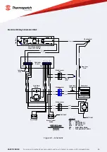
Page 20: ...3 GRY 4 GRY Seal Switch LS1 LS2 Motor Control Switch 8 BLU Wire Harness Plug 5 YEL 6 YEL RED YEL PT1600 RTD HS3C 4C Series Electrical Schematic 230 Volt Revision B CN2 CN1 SSR MTR HTR Press Arm Gnd L...

Page 21: ...anner Disassemble the machine into groups steel parts pneumatic components electrical components These can be handed in separately and reused 8 Declaration of Conformity We Thermopatch BV Draaibrugweg...

Page 22: ...luding but not limited to the accuracy or completeness of any information facts and or opinions contained therein Thermopatch BV its subsidiaries the directors employees and agents cannot be held liab...

Page 23: ...Thermopatch BV Draaibrugweg 14 1332 AD Almere The Netherlands T 31 36 549 11 11 sales thermopatch nl www thermopatch com...

Reviews: