MAN-IRD-012-05-E
4
Step 16
Check that the blower has correct rotation on three
phase units. If not, then switch two of the three legs
and try again.
Step 17
Check blower motor amperage. Check compressor
amperage. Reading must not exceed that indicated
on nameplate.
Step 18
Check compressor discharge line temperature. If
above 200°F (93°C) and if the sight glass is full,
adjust expansion valve to maintain 50-70°F (10-
21°C) above condensing temperature. If the sight
glass is empty or bubbling, then refrigerant has
been lost. Look for the leak, repair and recharge
system until sight glass is full. Do not overcharge.
Step 19
Adjust louvers in discharge duct so that air is
directly along the boards. DO NOT DIRECT OVER
THE ICE SURFACE!
Step 20
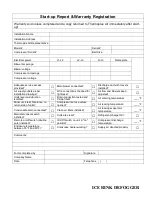
Fill in the start-up report and warranty registration
form, and forward a copy to sales agent, or
Thermoplus air
factory.
Warranty is not valid until start-up report received at
the factory.
Leave the owner's manual complete with start-up
report with the IRD unit.
The IRD Series is remotely started by the remote
on/off switch. Turn on the IRD units approximately
one to two hours before the ice rink is to be used,
and leave the units running continuously during the
active period or whenever high humidity is a
problem.
When the return air temperature is low, the IRD
Series actually freezes moisture out of the air. The
coils have been designed for frost build-up. An
automatic built-in defrost cycle engages periodically
to eliminate the ice build-up. When a defrost cycle is
initiated, the blower is shut off. The compressor
continues to run during the defrost cycle. Once the
defrost cycle is completed, the compressor stays in
operation and the blower restarts.
The IRD Series units are protected by an internal
temperature limiting thermostat which is factory set
at 30°F (-1°C). The IRD Series technology is so far
advanced that it requires virtually no maintenance.
Air Filters
The air filters should be checked once per month.
Dirty filters should be changed immediately and
replaced with identical filters, which should be
available locally. Clogged and dirty filters will
seriously hamper the performance of the
equipment.
Blower Belt
The following procedure should only be performed
by a factory trained service technician.
Check the belt for signs of wear and replace if
severely worn or cracked.
IMPORTANT!
The IRD Series units must be fine-tuned on
start-up for maximum energy efficiency and
moisture removal capacity. Adjust the
expansion valve for proper operation, a 8 to
12°F (-13 to -11°C) superheat is recommended
for optimal performance.


