background image

5

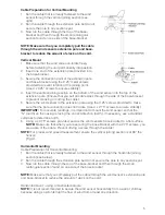
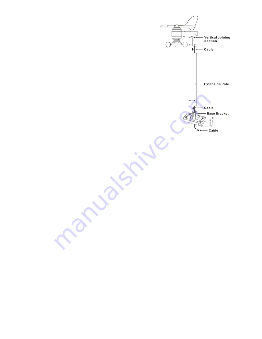
Cable Preparation for Vertical Mounting

1.   Run the cable that is already fastened to the wind 

sensor through the vertical joining section (see 
right).

2.   Run the cable through the extension pole but do not 

secure the pole to any sections yet.

3.   Now run the cable through the top of the base-

bracket and then through the small rectangular 
section found on one side of the base-bracket.

NOTE: Make sure that you completely pull the cable 
through the wind sensors extension pole and base-
bracket to reduce the amount of slack on the cord.

Vertical Mount

1.   Make sure that the wind vane can rotate freely 

before fastening the unit permanently into position.

2.   Insert one end of the extension pole provided into 

the base-bracket.

3.   Secure the connection point of the extension pole 

and base-bracket using the 0.25” metal screws 
provided to prevent rotation at the joining point. 
(Use 4 x 0.25” screws to ensure stability).

4.   Insert the vertical joining section on the bottom of the wind sensor into the top of the 

extension pole. (Ensure that you pull all cable slack through the side of the base-bracket 
to prevent creasing or cutting the cable).

5.   Secure the wind sensor to the extension pole using the 0.25” screws provided to make 

sure that the pole connection does not rotate. (Use 4 x 2.75” screws to ensure stability).

IMPORTANT:

 For accurate readings, it is important to mount the wind sensor so that the 

q&*+&*9+X
compass to determine north.
{9$];9?_YXY\Q+9
 

NOTE:

 Make sure that when you are securing the base bracket with the 2.75” screws, you 

are aware of the cable. Prevent driving a screw through the cable!

NOTE:

 For proper wind speed measurement ensure the vertical joining section is at 90º the 

horizon 
(Fig.A).

Horizontal Mounting

Cable Preparation for Horizontal Mounting
1.   Run the cable that is already fastened to the wind sensor through the horizontal joining 

section (see below).

2.   Run the cable through the extension pole but do not secure the pole to any sections yet.
3.   Now run the cable through the top of the base-bracket and then through the small 

rectangular section found on one side of the base-bracket.

NOTE:

 Make sure that you completely pull the cable through the wind sensor’s extension pole 

and base-bracket to reduce the amount of slack on the cord.

Horizontal mount - using a mast/antenna/pole

NOTE: 

It is not recommended to secure the wind sensor horizontally from a wall or chimney 

YQY+Y+ 9

Summary of Contents for bios atmosphere 2.0

Page 1: ...1 atmosphere Jumbo Weather Monitor Moniteur Météorologique Géant Instruction Manual Mode d emploi ...

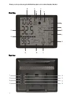
Page 2: ...2 B A O C F D E G H I J K L M N 1 2 3 6 8 5 7 4 Front View Back View Thank you for purchasing the BIOS Atmosphere 2 0 Jumbo Weather Monitor ...

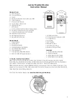
Page 3: ...dio Control Clock RCC RCC has the most accurate time within the continent This unit receives the time signal transmitted by the National Institute of Standards and Technology NIST which is regulated by 3 atomic clocks and in average deviates less than 1 second in 3000 years NIST transmits the time signal WWVB 60kHz continuously from Fort Collins Colorado This signal can be received in the USA and ...

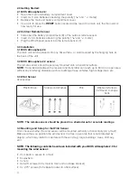
Page 4: ... buildings trees vehicles high voltage lines etc 3 3 Wind Sensor Accessories Plastic Base Screws and Washes Pole Washes Screws X2 Round U shape bolts NOTE The remote sensor should be placed in a shaded area for accurate readings 3 4 Mounting and Setup for the Wind Sensor First choose whether the wind sensor will be mounted vertically or horizontally on a mast Make sure that you position the wind s...

Page 5: ...revent creasing or cutting the cable 5 Secure the wind sensor to the extension pole using the 0 25 screws provided to make sure that the pole connection does not rotate Use 4 x 2 75 screws to ensure stability IMPORTANT For accurate readings it is important to mount the wind sensor so that the q 9 X compass to determine north 9 9 _ Y X Y Q 9 NOTE Make sure that when you are securing the base bracke...

Page 6: ...ction point of the pole extension and base bracket using the 0 25 screws provided to prevent rotation at joining point Use the 4 x 0 25 screws to ensure stability 5 Insert the pole extension into the horizontal joining section Ensure that you pull all cable slack through the side of the base bracket to prevent creasing or cutting the cable 6 Secure the horizontal joining section to the mount pole ...

Page 7: ... Fahrenheit C F button to select indoor outdoor temperature in Celsius or Fahrenheit mode C F button on the rear of the BIOS Atmosphere 2 0 remote sensor inside the battery compartment to select the temperature to be displayed in Celsius or Fahrenheit mode X 9 or HH H beyond the maximum temperature will be shown on the LCD 2 Max Min Outdoor Temperature MAX MIN button to select the desired view pas...

Page 8: ...am Initial setup may take several minutes to synchronize C F button until Q 9 es several minutes If the WWVB signal reception fails icon will disappear from the LCD and the clock will then attempt to scan the radio signal again on the next full hour E g if scanning failed at 8 20a m it will scan again at 9 00a m C F Q 9 DST ON OFF button selects to turn on or off DST Daylight Saving Time 9 qX will...

Page 9: ... to your Local Weather Station 10 Moon Phase Display 11 0 Low Battery Indication Y will appear indicating that the outdoor remote sensor is in a low battery status The batteries should be replaced 12 0 Battery Disposal Y 9 Dispose of old defective batteries in an environmentally friendly manner in accordance with the relevant legislation IMPORTANT Warning The BIOS Atmosphere 2 0 and the outside se...

Page 10: ...d Quartz back up Power C x 3 pieces for the monitor AA x 2 pieces for outdoor sensor 14 0 Precautions Y 9 sets Y 9 X X X Y X Y sunlight and rain q 9 cleaning agents may scratch plastic parts and corrode electronic circuits Y Y unit the Local Weather Station s forecast should prevail The manufacturer will not take responsible for incorrect forecasting from this unit 15 0 Industry Canada FCC Stateme...

Page 11: ...F 16 0 One Year Warranty If this product proves to be defective in material or workmanship within one year of purchase please return it to the address below It will be repaired or replaced without charge upon receipt of the unit prepaid with 5 00 to cover handling packaging and return postage Please include proof of purchase your full name address daytime phone number or email address This warrant...

Reviews: