background image

Concealed Wiring Installation


1. Switch off the mains power

You will be installing the Thermorail as part of a high voltage mains electrical circuit. 

To ensure your safety and to protect the Thermorail, switch off the mains power 

before you start the installation. Please ensure that means for disconnection are 

incorporated in the fixed wiring in accordance with the wiring rules.

2. Install the transformer

The transformer is to be installed in the ceiling or the wall cavity no further than 2m 

from the rails and needs to be connected to the mains power supply in accordance with 

current local building regulations. If mounting in the wall cavity the transformer must be 

behind an access plate or a timer/switch to enable access and the transformer must 

have ventilation.

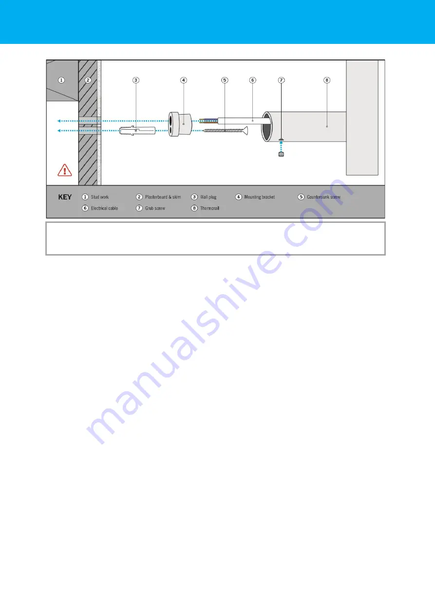
3. Install two wall brackets

Measure and mark out the bracket positions making sure they are level. Drill a 6mm 

hole for each of the two wall brackets and an extra hole for the cable at the wiring 

point and insert suitable wall plugs. Fix the two mounting brackets in place using a 

screwdriver and screws.

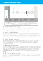
4. Electrical Connections

Ensure your electrical supply is switched off. Push the cable through the hole in the  wall 

bracket and connect to the transformer previously installed (refer to the wiring diagrams 

opposite). When installing multiple of the Thermorail Vertical Rails it is recommended 

that each rail is connected to its own individual transformers. Multiple rails connected to 

individual transformers can be wired to a single timer/switch and must be wired in 

parallel. 

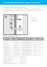
5. Fix Thermorail to the wall

Fit the Thermorail to the mounting brackets installed on the wall. You may need assistance 

to hold the rail in place. Tighten the grub screws on the two wall mount arms using the 

allen key provided.

4

WARNING:

 This is a 12Volt heated towel rail and MUST be wired to a transformer 

(supplied). Connecting directly to the mains power supply will cause irreparable damage 

to the element and the element cannot be replaced. 

Summary of Contents for VS900H

Page 1: ...Thermorail Vertical Rail VS900H VS900HB VS900HBR VS900SH VS900HBG VS900HGM VS900HSW VS900HBN 12Volt Heated Towel Rail Installation Guide ...

Page 2: ...Contents What s in the box Concealed Wiring Installation Wiring Diagram Technical Specifications Safety Care Information Warranty Information Warranty Registration Contact Us 3 4 5 5 6 7 7 8 2 ...

Page 3: ...Electrical Supply Timer Switch 1 x Non Wired Mounting Bracket 1 x Wired Mounting Bracket 2 x Wall Plugs 2 x Countersunk Screws 1 x Small Machine Screw Grub Screws 1 x Hook 1 x Allen Key Please note for some models the legs are supplied separate to the main rail Non Wired Mounting Bracket 3 Wired Mounting Bracket Wall Plug Countersunk Screw Small Machine Screw Grub Screw Allen Key Please note these...

Page 4: ...h of the two wall brackets and an extra hole for the cable at the wiring point and insert suitable wall plugs Fix the two mounting brackets in place using a screwdriver and screws 4 Electrical Connections Ensure your electrical supply is switched off Push the cable through the hole in the wall bracket and connect to the transformer previously installed refer to the wiring diagrams opposite When in...

Page 5: ...wired 1 Year NO OF BARS SIZE MM Polished Polished Matt Black Brushed Brushed Gold Satin White Gun Metal Brushed Nickel FINISH OUTPUT WATTAGE WARRANTY Transformer Wiring Diagram Key 1 Wall Cavity 2 Transformer 3 Switch Timer 4 Thermorail Please note that the hook is optional and is not necessary for the unit to operate Slide the hook on the top of the vertical bar ensuring that the small screw hole...

Page 6: ... so when near young children or infirm persons close supervision is necessary Do not immerse your Thermorail in any liquid Ensure the transformer is located no further than 2m from the Thermorail s Ensure the transformer is accessible and has adequate ventilation Ensure that multiple rails connected to individual transformers are wired in parallel to the switch timer This appliance is not intended...

Page 7: ...egistration form If the product develops a fault within the warranty period due to normal wear and tear Thermogroup at its discretion will recognise whether it s a faulty product or not If it is impossible or not economical for the manufacturer to repair the product the manufacturer will replace the faulty product with a new unit of the same model or if there is no stock available of the same mode...

Page 8: ...Contact Us Thermogroup 1300 368 631 sales thermogroup com au www thermogroup com au 8 ...

Reviews: