Installation, use and maintenance guide
ARDHEA EVO5
– ARDHEA-F EVO5
Page
16
ENG
6
–
ASSEMBLING THE COMPONENTS
6.1 INSTALLATION OF THE SAFETY HEAT EXCHANGER (OPTIONAL)
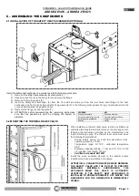
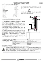
Install the safety heat exchanger in accordance with the following procedure:
1) Remove the
safety heat exchanger insertion plate (1)
.
2) Slightly loosen the nut in the flange (2) and remove the flange.
3) Remove the two rear plugs (4).
4) Insert the safety heat exchanger (3) from the front side and slide out from the rear holes both fittings of the heat
exchanger, and fix it to the boiler using the fixing elements (5) in the following order: gasket O-ring, conical washer with the
concave side towards the gasket and nut.
5) Remount the flange (2) and the plate (1).
6) ATTENTION: before reassembling the remaining parts make
sure that the gaskets are tight by bringing the system to
pressure.
6.2 MOUNTING THE THERMAL RELIEF VALVE
When installing a thermal relief valve, install a certified and
calibrated two-way thermal relief valve at the exchanger inlet,
following the instructions provided by the manufacturer and
install a discharge pipe. The thermal relief valve must have
the following characteristics:
-
Double safety sensor for solid fuel generators (max.
operating pressure): 10 bar
-
Temperature range: 5÷110°C - calibration temperature
98°C
-
Discharge capacity with Δp = 1 bar and T=110°C: 3,000
l/h - capillary tube length: 130 mm
-
Certified to standard EN 14597
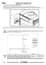
Install the valve sensitive element in the special pocket
located at the back, as indicated in the figure.
ATTENTION: A CONNECTION MUST BE MADE BETWEEN
THE SAFETY VALVE AND THE OUTLET TO PREVENT
DAMAGING
MATERIALS
SURROUNDING
THE
APPLIANCE
WHEN
THE
VALVE
IS
ACTIVATED.
ATTENTION: IF THE SAFETY HEAT EXCHANGER IS
INSTALLED TO PRODUCE DOMESTIC HOT WATER, THE
GUARANTEE FOR THE GENERATOR IS IMMEDIATELY
VOIDED.
LEGENDA
KEY
Elemento sensibile
Sensitive element
Corpo valvola scarico termico
Thermal relief valve body
Entrata acqua acquedotto
Water main inlet
Scarico
Outlet


