Installation, use and maintenance guide
COMPACT S22
–S26–S32 EVO5
Page
35
ENG
7 ADDITIONAL ROOM TEMPERATURE THERMOSTAT / ADDITIONAL
CHRONOTHERMOSTAT
Your appliance is already fitted with all the temperature adjustment and programming functions. However, the appliance can be
connected to an additional room temperature thermostat or to an additional chronothermostat:
-
Additional
room temperature thermostat
: connect the terminals directly to the terminal block on the circuit board, as
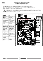
illustrated in the image below.
-
Additional
Chronothermostat - Modem
: connect the terminals directly to the terminal block on the circuit board, as
illustrated in the image below.
The contacts of the room temperature thermostat and of the chronothermostat modem, are defined as
"potential free" contacts and they must never be supplied with 230V. If the board is powered with 230 V or
lower voltages, the control board would be irreparably damaged and the warranty voided.
When the external room temperature thermostat or the external room temperature chronothermostat, connected to the
terminal block of the Chronothermostat Modem, activate they start up the generator and the text
EXT
appears on the
display.
This operation must be exclusively performed by qualified professional staff, as set forth by Decree no. 37 of 22nd
January 2008 and applicable laws on the subject. Before performing said task, make sure the power supply cable is
disconnected from the electrical power socket.
7.1 OPERATING WITH THE ADDITIONAL ROOM TEMPERATURE THERMOSTAT (NOT SUPPLIED)
An additional room temperature thermostat can be installed by connecting it to the inside of the electronic board compartment,
using contacts 7 and 8 on terminal block CN7 as illustrated in the figure below. It has a “potential free” contact, that is a very low
voltage contact. The operating principle is as follows:
• When the room temperature reaches the set temperature, the room thermostat
closes
the contact, the appliance will operate at
the minimum combustion power and the 1st power bar will flash on the display, any manual power change will be disabled.
• When the room temperature drops the thermostat
opens
the contact and the appliance returns to its original position in terms of
thermal power.
ATTENTION: N.C. “
Normally Closed
” contacts must be used for the connection to the additional room temperature
thermostat. Do not power the contacts with mains voltage as this would seriously damage the control board, and is not
covered by warranty.
7.2 OPERATING WITH THE ADDITIONAL CHRONOTHERMOSTAT (NOT SUPPLIED)
An additional chronothermostat can be installed by connecting it to the inside of the electronic board compartment, using contacts 9
and 10 on terminal block CN7 as illustrated in the figure below. Using this output when the chronothermostat contact
closes
the
START cycle begins, whereas when the contact
opens
the OFF cycle begins. When the chronothermostat is active the appliance
cannot be switched off manually but only from the additional chronothermostat.
ATTENTION
: The manufacturer denies all responsibility for the life of the electrical heater if subjected to excessive start
up cycles. Consequently, it is advisable to set the chronothermostat appropriately. If an external chronothermostat is
connected to the appliance it will not be possible to use the Chrono function on the panel.
ATTENTION:
Use N.O. (
normally open
) contacts for the connection to the chronothermostat. Do not supply direct
power of 230 V or lower voltages as this would seriously damage the control board, and is not covered by warranty.
ATTENTION
: In the event of connections to the chronothermostat Thermorossi shall not be held responsible for the appliance not
starting up, smoke leaks, breakage of the lighting component. The user must make sure that the brazier is always clean.
ATTENTION:
When using the chronothermostat program
up to a maximum of 3 on-off cycles
. The chronothermostat must have
a thermal hysteresis that is not less than 2°C.

