background image

Installation, use and maintenance guide 

COMPACT S22

–S26–S32 EVO5 


Page 

42


ENG 


9 – SMOKE DISCHARGE TUBE AND VENTILATION OF THE ROOMS 

9.1 FOREWORD 

Due  to  the  frequent  accidents  caused  by  poor  functioning  of  flue  outlets  installed  in  private  dwellings,  we  have 
prepared  the  following  paragraph  to  assist the  installer in his  inspection  of the parts concerned  with eliminating  the 
gases produced by combustion. 
 
The  smoke  outlet  must  be  fitted  in  compliance  with  standard  UNI  7129/92,  UNI  10683  and  EN  14785  and  it  must 
observe  the  reference  values  laid  down  in  the  standard,  in  particular,  the  outlet  must  comply  with  fire  prevention 
regulations. 

It is important to carefully follow the instructions set out below: failure to observe these instructions could 
cause serious damage to the product, to the system, to objects and to persons using the generator.


9.2 ROOM VENTILATION 

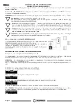
ATTENTION: the presence of extraction fans or similar appliances, if operating in the same room or space in which 
the product is installed, could cause problems for the correct operation of the product. 
ATTENTION: do not obstruct the vents or the air inlets on the appliance. 

 
The room where the appliance is installed must have a good air flow to guarantee air for the appliance for the combustion process 
and  for  ventilation  of  the  room.  The  natural  air  flow  must  take  place  directly  through  permanent  openings  on  the  outer  walls  or 
through single or multiple ventilation ducting (paragraph 9.2.1). 
The ventilating air must come from outside and if possible, away from sources of pollution. The openings in the walls must comply 
with the following conditions: 
• have an unobstructed section of at least 6cm² for each Kw of installed thermal power, with a minimum limit of 100cm²; 
• be made in such a way that the vent openings, both on the inside and outside of the wall, cannot be obstructed; 
• be protected with grills or similar systems that do not reduce the opening section indicated above; 
•  be  situated  at  a  height  near  floor  level  and  they  must  not  obstruct  the  correct  operation  of  the  combustion  product  discharge 
devices; if this position is not possible the section of the ventilation openings must be enlarged by at least 50%. 

9.2.1 VENTILATION FROM ADJOINING ROOMS 

The air flow can also be obtained from an adjoining room as long as: 
• the adjoining room is equipped with direct ventilation in compliance with the paragraphs described above; 
• only appliances connected to the exhaust pipe are installed in the room that is ventilated; 
• the adjoining room is not used as a bedroom or a common area of the building; 
• the adjacent room is not a room with a fire hazard, such as storage sheds, garages, combustible material store rooms, etc...; 
• the adjoining room does not become a vacuum compared to the room to be ventilated due to a reverse draught effect (the reverse 
draught can be caused by the presence in the room of either another heating appliance running on any type of fuel, a fireplace, or 
any suction device, which have not been provided with an air intake) 
•  the  air  flow  from  the  adjoining  room  to  the  room  to  be  ventilated  is  unobstructed  through  the  permanent  apertures  having  an 
overall net section of no less than that indicated above. These apertures can be obtained by enlarging the space between the door 
and the floor. 

9.2.2 SINGLE OR MULTIPLE VENTILATION DUCTING 

If  the  combustion  air  is  supplied  through  pipes,  the  available  draught,  produced  by  the  installed  appliance  in  use  and  by  the 
corresponding  combustion  product  evacuation  system,  must  be  greater  than  the  sum  of  the  resistance  offered  by  the  pipes 
(frictional resistance, resistance due to direction changes, cross-sectional restrictions, etc...). 
The single ventilation pipes can be vertically and horizontally oriented: the length of the horizontal sections must be reduced to a 
minimum. 
The connectors between pipes with different orientations must not have any reduced cross-sections with sharp bends. 
The angle of connection between the axes of two successive pipes must not be less than 90°. 
For combustion air supplied through branched pipes, the sum of the resistance offered by the pipes (frictional resistance, resistance 
due to direction changes, cross-sectional restrictions, etc....) can be a maximum of 10% of the available draught, produced by the 
various appliances in use installed on the various floors and by the combustion product evacuation system. 
The branched ventilation pipes must be vertically-oriented with an uphill run. 
The inlet vent to the room to be ventilated must be located down low and in a position where it does not interfere with the d ischarge 
of combustion products and must be protected by a grill or similar device. 
 

9.3 SMOKE OUTLET 

The  smoke  channel,  the  exhaust  pipe,  chimney  and  flue  outlet  (defined  as  the  system  for  the  evacuation  of 
combustion products), are parts of the heating system and they must comply with the legislative requirements of the 
Ministerial Decree DM 37/08 (ex Italian Law 46/90) and to the applicable specific installation regulations, according to 
the type of fuel. Fireplaces, stoves and barbecues must not be installed in locations where gas appliances type A and 
type  B  are  present  and operating  (for  the classification see  UNI  10642 and  UNI  719).  The  connection between  the 
appliance and the flue outlet must only receive exhaust from one heat generator. 

Summary of Contents for COMPACT S22 EVO5

Page 1: ......

Page 2: ...Installation use and maintenance guide COMPACT S22 S26 S32 EVO5 Page 1 ENG ...

Page 3: ...DESCRIPTION 8 4 INSTALLATION 10 5 HYDRAULIC CONNECTION 14 6 USE OF THE APPLIANCE 21 7 ADDITIONAL ROOM TEMPERATURE THERMOSTAT ADDITIONAL CHRONOTHERMOSTAT 35 8 CLEANING AND MAINTENANCE 37 9 SMOKE DISCHARGE TUBE AND VENTILATION OF THE ROOMS 42 10 ALARMS 45 11 ELECTRICAL WIRING 46 12 INFORMATION FOR THE SKILLED TECHNICIAN 48 13 SPARE PARTS 52 ...

Page 4: ...E EU 2015 1187 FR FICHE PRODUIT UE 2015 1187 NL PRODUCTGEGEVENSBLAD EU 2015 1187 DE PRODUKTDATENBLATT EU 2015 1187 ES FICHA DE PRODUCTO UE 2015 1187 IT MARCHIO EN BRAND FR MARQUE NL MERK DE MARKE ES MARCA THERMOROSSI S P A IT MODELLO EN MODEL FR MODÈLE NL MODEL DE MODELL ES MODELO COMPACT S22 EVO5 COMPACT S26 EVO5 COMPACT S32 EVO5 IT CLASSE DI EFFICIENZA ENERGETICA EN ENERGY EFFICIENCY CLASS FR CL...

Page 5: ...identifies important messages throughout the manual Read the information marked by this symbol carefully as non observance of this message can cause serious injury to persons using the appliance DAMAGE TO PROPERTY This safety symbol identifies messages or instructions that are fundamental for the generator to function well To avoid serious damage to the appliance adhere strictly to these instructi...

Page 6: ... damage the vacuum device All the cleaning operations described in this manual must be carried out when the appliance is cold and shut off Attention Warning for Swiss users Refer to the local cantonal regulations imposed by the Fire Department Mandatory signalling and safety distances and the Note concerning installation of heaters issued by the Association of Cantonal Fire Agencies VKF AEAI ATTEN...

Page 7: ... 55 Smoke flow at rated power g sec 13 4 15 1 16 6 Smoke flow at reduced power g sec 7 2 7 2 7 2 Efficiency at rated power 93 5 93 2 92 8 Efficiency at reduced power 90 9 90 9 90 9 CO at rated power with 10 O2 mg m 32 28 21 CO at reduced power with 10 O2 mg m 318 318 318 Power supply voltage and frequency V Hz 230 50 230 50 230 50 Electrical consumption at Rated power W 70 70 96 Electrical consump...

Page 8: ...04 621 831 866 RIORE VISTA SUPERIORE SCALA 1 20 621 866 319 375 236 108 175 108 425 150 217 O 1 0 0 496 394 831 3 4 F ritorno 3 4 carico scarico caldaia 3 4 F mandata 3 4 carico scarico impianto 328 O 8 0 Legenda Key 3 4 F ritorno 3 4 F return 3 4 F mandata 3 4 F delivery 3 4 carico scarico impianto 3 4 system inlet outlet 3 4 carico scarico caldaia 3 4 boiler inlet outlet ...

Page 9: ...ea can get very hot ATTENTION It is normal to find some pellets remaining in the tank even if the appliance shuts off because the pellets have run out Attention when filling up the tank take care not to drop any pellets into the internal parts of the appliance as in extreme cases this could generate live flames The manufacturer recommends emptying the tank and vacuuming the screw feeder zone once ...

Page 10: ...be scraper lever F Safety pressure switch T Power panel F1 Safety pressure switch U Combustion chamber Patented burner G Manual reset button V Riddling tool H Pellet loading motor W Boiler drain refill tap I Tank pellet X Plant water return J Main switch 0 I Y Safety valve 3 bar K Plant water delivery Z System inlet L Electronic board AC 8 l expansion tank for boiler protection only M Pressure gau...

Page 11: ...nuary 2008 d References to existing partial or previous declarations of conformity e g electrical wiring e Copy of the certificate of recognition of the professional technical qualifications These documents must by law be kept together with the use and maintenance booklet The customer is responsible for verifying directly or indirectly that the installation has been carried out to perfection in ac...

Page 12: ...ne 66576193 340 kg 69979207 36 mm 3 tr dc01 DatiOffice Reparti Tecnico DWG Solid_edge COMPACT RESTYLE 70020296 asm CALDAIA IMBALLATA Descrizione Revisione Autore Data Descrizione LAMIERA Il fornitore è responsabile della corretta realizzazione del particolare come indicano le viste di progetto lo sviluppo piano deve essere verificato ed eventualmente modificato dal fornitore in funzione delle macc...

Page 13: ...parte del fornitore prima di realizzare qualsiasi attrezzatura fornire a THERMOROSSI S p A i file tridimensionali dei particolari definitivi X Figura 5 Il presente disegno è di proprietà esclusiva di THERMOROSSI S p A La riproduzione totale e o parziale e la divulgazione a terzi senza nostro esplicito consenso scritto verrà perseguito secondo i termini di legge in vigore 13 03 2015 Scala Locazione...

Page 14: ...ide the building Connect the air intake on the appliance to the exterior of the building with suitable piping capable of resisting high temperatures The pipe s length must be maximum 600 mm ATTENTION The suction duct must be protected with a grid and never be clogged The protection grid if installed must be inspected and cleaned on a monthly basis Moreover a suitable windbreak fitting must be inst...

Page 15: ...alve and the outlet to prevent damaging materials surrounding the boiler when the valve is activated ATTENTION To avoid continual startups and shut offs the size of the plant must be such as to guarantee power absorption that is not less than the power generated by the boiler running at reduced power 1 System circulating pump W System drain refill gate valve 2 Automatic relief valve X Plant return...

Page 16: ...ture To adjust the ambient temperature in which the valve opened we recommend connecting the room temperature thermostat to the CHRONOTHERMOSTAT MODEM terminal that allows the machine to be shut off via an external contact and therefore also restarted This ensures that the generator only activates if there is a real request for heat from the zone in which the chronothermostat is installed Several ...

Page 17: ... ATTENTION it is mandatory to earth the generator If this instruction is not observed serious damage which is not covered by warranty will result to the body of the appliance Have a skilled electrician check the earthing There must be no electric potential Volt between the generator earth and the system s real earth earth plate To prevent electrochemical corrosion of the appliance body do not use ...

Page 18: ...e boiler tubes can be installed on the water return circuit It is recommended to install a water softener in the domestic water system in order to maintain the boiler at its peak efficiency ATTENTION it is mandatory to earth the generator If this instruction is not observed serious damage which is not covered by warranty will result to the body of the appliance Have a skilled electrician check the...

Page 19: ...he generator could raise the water temperature to such a point as to activate the safety limit thermostat which stops the fuel from dropping into the burner and therefore forces the appliance to shut off The installer is required to install a valve that switches over to the system powered by the appliance s control unit which trips when the boiler tube is thermally satisfied Consequently the syste...

Page 20: ...dell impianto a pavimento Safety thermostat for protection of the under floor heating system ATTENTION the preload pressure of the expansion tank must be greater than the plant pressure for an expansion tank preloaded to 2 bar the plant must be loaded to a pressure that does not exceed 1 5 bar ATTENTION The Thermocell is only fitted with a connection to 230V 50Hz power line the settings of Sensor ...

Page 21: ...must be installed by qualified personnel who are familiar with the standards mentioned above and who have the appropriate professional requirements to release the declaration of conformance in accordance with Ministerial Decree n 37 of 22 January 2008 The generator is already supplied with the following safety devices on board a closed expansion tank for generator protection only b ordinary safety...

Page 22: ...emperature detection system uses thermocouples The large display improves the appliance management by making read outs and functions promptly available The main feature of the panel is the all automatic management of the appliance The controls and the various displays are described below Flame button Pressing this button when the appliance is off activates the START sequence sets the operating pow...

Page 23: ...rget temperature set by the user see para 6 10 Indicates the temperature of the domestic hot water boiler if the optional sensor is connected Indicates the temperature of Sensor S1 for control of a puffer if the optional sensor is connected Indicates the temperature of Sensor S2 for control of a puffer if the optional sensor is connected Indicates that the circulation pump is activated when the wa...

Page 24: ... e g 1 corresponds to Monday 2 corresponds to Tuesday etc To confirm the selected day of the week press the Degrees Button Once confirmed the selector shifts to the hour section while the selected day of the week remains framed 4 Press the Scroll Buttons to change the hour Once you have set the hour confirm the value by pressing the Degrees Button Once confirmed the selector shifts to the minutes ...

Page 25: ...the start up time Once confirmed the selector shifts to the minute section of ON2 Press the Scroll Buttons to set the minutes for the second start up Confirm by pressing the Degrees Button Now press the Scroll Buttons to select the hour at which you wish the appliance to shut off automatically OFF2 Once the hour has been set confirm the value by pressing the Flame Button Once confirmed the selecto...

Page 26: ...ock symbol appears on the display it will not be possible to use an additional chronothermostat see dedicated paragraph The appliance will strictly follow the programmed ON OFF times No request for heat by the system a puffer or a domestic hot water boiler will be considered by the appliance if it is outside the programmed time interval Disabling the programmed cycles To disable the appliance from...

Page 27: ...ly compressed pellets and or when the flue outlet has a very high vacuum over 2 mm water column 20 Pascal The pellet consumption value remains unchanged regardless of the selected operating level These variations will only change the rotation of the smoke suction unit in the WORK stage see para 6 10 all the other stages will not undergo any changes Select the required Level by acting as follows 1 ...

Page 28: ...e is subjected to with this function It is recommended not to exceed three ON OFF cycles If the startups are frequent and repeated it is possible that the the generator will fail to start and the following error message appear Failed start Clean burner The appearance of this message is not attributable to a product defect but is caused by a brazier that requires cleaning as described in this manua...

Page 29: ...the following screen appears 4 Press the Scroll Buttons to set the minimum activation temperature for the sensor The sensor is installed in the central part of the boiler and commands the appliance to start up as the boiler tube is exhausting the available heat The setting range is from 45 C to 65 C 5 Confirm the selection by pressing the Degrees Button and the following screen will appear 6 Press...

Page 30: ...ure detected When is it important to use the ACS SUMMER function In systems configured like the nearby diagram where the appliance is connected directly to a domestic hot water boiler tube and to the system Using this function the generator starts up automatically when the boiler tube is running out of heat and only in the programmed time bands Once the boiler tube is satisfied the appliance does ...

Page 31: ...appliance takes its power to the minimum then switches off when the temperature reaches 24 C It will only restart when the temperature drops below 20 C at the power previously set by the user ATTENTION Do not place the room temperature sensor near any heat or cooling sources that could at any time affect the temperature detected by the sensor When is it important to use the TAMBIENT function In sy...

Page 32: ...es that the appliance is subjected to with this function It is recommended not to exceed three ON OFF cycles If the startups are frequent and repeated it is possible that the generator will fail to start and the following error message appear Failed start Clean burner The appearance of this message is not attributable to a product defect but is caused by a brazier that requires cleaning as describ...

Page 33: ...ation of the OFF cycle the brazier cleaning mechanism Pellet Power that is the device installed inside the brazier moves in continuous mode After approx 25 minutes the appliance goes to standby and the brazier cleaning mechanism Pellet Power stops ATTENTION It is recommended to verify at least once a month that when the appliance is in OFF mode in the time interval specified above the brazier clea...

Page 34: ... if the THERMOCONTROL function is active in the appliance Example If for example the temperature is set at 70 C the five speed levels will be automatically distributed between 61 C and 70 C so that with a temperature set at 70 C the appliance is at its minimum power level If the temperature value is increased or reduced all the power levels will be redistributed along the new temperature range We ...

Page 35: ...o set the appliance in AUTO or manual operating mode The mode will be activated at the end of the start up phase By pressing the Degrees Button you can regulate the desired water temperature in the boiler During the 20 minutes of the start up phase any set thermal power level is ignored to deal with correct fill up and suction values preset by the Manufacturer The electrical heater will start to o...

Page 36: ...the set temperature the room thermostat closes the contact the appliance will operate at the minimum combustion power and the 1st power bar will flash on the display any manual power change will be disabled When the room temperature drops the thermostat opens the contact and the appliance returns to its original position in terms of thermal power ATTENTION N C Normally Closed contacts must be used...

Page 37: ...zone valves with this type of installation it is mandatory to deactivate the valves by opening them completely Consequently the dissipation of heat at least equal to or greater than the minimum power output to the water in the appliance must be guaranteed at all times The chronothermostat must have a thermal hysteresis that is not less than 2 C Legenda Key Cronotermostato Modem Chronothermostat Mo...

Page 38: ...vered by warranty Unless otherwise instructed the operations described below are mandatory and not postponable beyond the specified times EVERY DAY Thoroughly clean the burner Figure 1 with a vacuum cleaner carefully clean the area around the spark plug This is to ensure that the appliance operates correctly and to avoid start up failures Move the tube scraper lever up and down vigorously at least...

Page 39: ...re firmly closed and airtight ATTENTION the generator the smoke channel and flue outlet must be cleaned in accordance with the specifications described above and use of inflammable products is strictly forbidden using inflammable products can create dangerous situations Failure to carry out the necessary maintenance or if only partial maintenance is carried out will affect the correct functioning ...

Page 40: ...re come indicano le viste di progetto lo sviluppo piano deve essere verificato ed eventualmente modificato dal fornitore in funzione delle macchine di piegatura che andranno a realizzare il particolare STAMPI E FUSIONI É obbligo da parte del fornitore prima di realizzare qualsiasi attrezzatura fornire a THERMOROSSI S p A i file tridimensionali dei particolari definitivi Figura 1 Figura 2 ...

Page 41: ...Installation use and maintenance guide COMPACT S22 S26 S32 EVO5 Page 40 ENG Figura 3 Figura 4 C1 C2 Figura 3 Figura 4 C1 C2 ...

Page 42: ...Installation use and maintenance guide COMPACT S22 S26 S32 EVO5 Page 41 ENG Figura 4 Figura 5 C3 ...

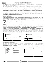
Page 43: ... building the adjacent room is not a room with a fire hazard such as storage sheds garages combustible material store rooms etc the adjoining room does not become a vacuum compared to the room to be ventilated due to a reverse draught effect the reverse draught can be caused by the presence in the room of either another heating appliance running on any type of fuel a fireplace or any suction devic...

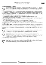
Page 44: ...e and possibly also insulation and outer casing wall that may be supplied by different manufacturers or by the same manufacturer Relining operation involving the installation of a specific pipe in an existing shaft even if newly constructed made of non combustible materials free from obstructions and for single use 9 3 2 FLUE OUTLET FLUE SYSTEM COMPONENTS Every chimney must have minimum number of ...

Page 45: ...ally insulated ISPEZIONE INSPECTION ALTEZZA SUPERIORE A 4 metri HEIGHT MORE THAN 4 m Pendenza non inferiore al 5 Minimum slope 5 2 metri MAX 2 metres MAX 2 3 metri MAX 2 3 metres MAX INTERNO INTERNAL ESTERNO EXTERNAL LASTRA DI COPERTURA COVER SLAB LAMIERA DI ACCIAIO A TENUTA STAGNA WATERTIGHT STEEL SHEET Seal area where the inlet and outlet part of the smoke exhaust meets the wall It is strictly f...

Page 46: ... switched off then on by turning the switch 0 1 located on the power panel Before restarting the appliance check for any irregularities such as blocked flue outlet open firebox door Do not start up the appliance until the problem has been identified and solved It is mandatory to empty and clean the brazier before repeating the START phase This appears when the water temperature in the appliance ex...

Page 47: ...657 Via Grumolo 4 36011 ARSIERO Vicenza ITALY S p A Spessore Approv Data approv Formato VARIE CORRETTE Cod Disegnatore Volume Peso Colore Revisione Descrizione Revisione Autore Data Descrizione LAMIERA Il fornitore è responsabile della corretta realizzazione del particolare come indicano le viste di progetto lo sviluppo ano deve essere verificato ed eventualmente modificato dal fornitore in funzio...

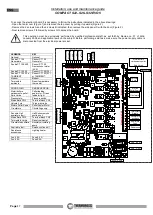
Page 48: ... Pressure switch Morsettiera CN3 Terminal block CN3 Valvola 3 vie Three way valve Motore Pellet Power Pellet Power Motor Circolatore Circulating pump Sensore Hall aspiratore fumi Hall Sensor smoke suction unit Morsettiera CN2 Terminal block CN2 Termostato riarmo Reset thermostat Circolatore ausiliario Auxiliary circulating pump Aspiratore fumi Smoke suction unit Resistenza accensione Lighting heat...

Page 49: ...FETY THERMOSTAT WITH MANUAL RESET When the temperature exceeds 98 C the pellet feed screw shuts down After having verified and solved the causes for the overtemperature reactivate the appliance by unscrewing the plastic cover of the thermostat and press the button the temperature of the appliance must have dropped considerably SPARK PLUG It is activated in the START phase It heats the incoming air...

Page 50: ...ontained in the enamel coating of the combustion chamber Do not install a grill or outlet terminal that could slow down the flow of the combustion gases this would obviously cause the appliance to malfunction Keep the appliance clean and check the burner as described in these instructions Clean the smoke outlet regularly Use good quality pellets use of poor pellets can result in up to 50 less effi...

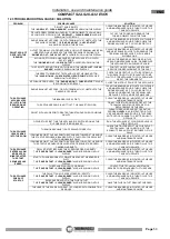
Page 51: ...TH A MORE SUITABLE ONE THE BRAZIER IS VERY DIRTY CLEAN THE BRAZIER AS INDICATED IN THIS USE AND MAINTENANCE GUIDE THE APPLIANCE DOOR IS NOT TIGHT THE GASKET IS WORN FIRMLY CLOSE THE DOOR OR CONTACT THE TECHNICAL ASSISTANCE SERVICE FOR REPLACEMENT OF THE SEAL PELLET WITH ASH DEPOSIT GREATER THAN STANDARD OR OF DUBIOUS QUALITY CLEAN THE BRAZIER AND SET OPERATING PROGRAM LEVEL 2 AS INSTRUCTED IN THIS...

Page 52: ...NEL FACEPLATE IS DEAD CONTACT THE TECHNICAL ASSISTANCE SERVICE FOR REPLACEMENT OF THE BATTERY THE HOURLY PROGRAM IS NOT COMPLIED WITH THE USER HAS NOT ENABLED IT PRESS THE CLOCK BUTTON TO ENABLE IT AS INSTRUCTED IN THIS USE AND MAINTENANCE GUIDE THE BUFFER BATTERY INSTALLED IN THE CONTROL PANEL FACEPLATE IS DEAD CONTACT THE TECHNICAL ASSISTANCE SERVICE FOR REPLACEMENT OF THE BATTERY AN INCORRECT P...

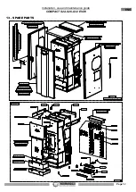
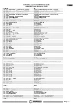
Page 53: ...1019 Controportone 70020191 Maniglia 70021018 Frontale trapezio inf 70020222 Frontale trapezio sup 70020195 Logo Thermorossi 60011793 Paracolpo 70021014 Fianco rivestimento dx completo 70018696 Fianco rivestimento dx 60012609 Magnete 60011793 Paracolpi 60012940 Isolante 70021015 Fianco rivestimento sx completo 70018697 Fianco rivestimento sx 60012609 Magnete 60011793 Paracolpi 60012940 Isolante 70...

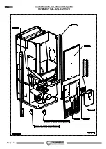
Page 54: ...mpleto 60011657 Presa spina tedesca 60011656 Interruttore 0 1 60011430 Spia luminosa verde 70012128 70012129 70021027 60013559 fino matricola 18223037000000170 60007462 Termostato riarmo 70012125 70012125 60013559 fino matricola 18223037000000170 70025303 da matricola 18223037000000171 70025303 da matricola 18223037000000171 04 06 2019 ...

Page 55: ...e Fino alla matricola 1623630213 60012585 60013845 70010234 60011793 70012080 60011428 60011645 60011671 70010402 60010185 70020263 70020264 70021037 70021339 70021029 60014350 Scheda potenza Fino alla matricola 1720630439 70014051 70022823 Scheda potenza HS Dalla matricola 1720630440 70020825 Circolatore Alta Eff Dalla matricola 1623630214 ...

Page 56: ... 32 DFT 60011246 70010234 60010185 60010185 60011646 70012146 60011649 60004581 60004581 60011643 70012088 60011644 60010185 60011649 60011643 70012148 60011644 70012147 60010185 60004581 60004581 6 0 0 0 6 6 8 2 6 0 0 1 1 7 9 5 70012164 60011678 70021009 60013555 70017765 70016846 60011796 60013342 ...

Page 57: ...609 Magnete 60012609 Magnet 60011793 Paracolpi 60011793 Bumper 60012940 Isolante 60012940 Insulation 70021106 Completo 70021106 Complete 70021017 Portone 70021017 Door 60011282 Cerniera 60011282 Hinge 70021019 Controportone 70021019 Internal panel 70020191 Maniglia 70020191 Handle 70021018 Frontale trapezio inf 70021018 Lower trapezoidal panel 70020222 Frontale trapezio sup 70020222 Upper trapezoi...

Page 58: ...umber 1623630213 70020825 Circolatore Alta Eff Dalla matricola 1623630214 70020825 High Eff circulating pump From serial number 1623630214 60014350 Scheda potenza Fino alla matricola 1720630439 60014350 Power board Up to serial number 1720630439 70022823 Scheda potenza HS Dalla matricola 1720630440 70022823 Power board HS From serial number 1720630440 Pagina 4 Page 4 ...

Page 59: ...nstallation use and maintenance guide COMPACT S22 S26 S32 EVO5 Page 58 ENG Via Grumolo 4 Z I 36011 Arsiero VI ITALY Fax 0445 741657 www thermorossi com info thermorossi it Fire Lovers Code 70021532 08 21 ...

Reviews: