Installation, use and maintenance guide
COMPACT SLIM S25 EVO
Page
18
ENG
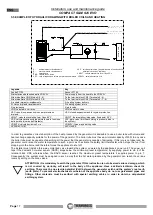
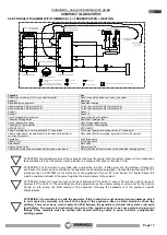
5.6 HYDRAULIC DIAGRAM WITH THER THERMO HEATING
Legenda
Key
Attenzione: chiudere tutti i fori non usati del puffer
Note: close all the holes not used by the puffer
Radiatori
Radiators
Riscaldamento pavimento
Underfloor heating
Alla morsettiera CN5 (morsetti 3-4)
To the terminal block CN5 (Terminals 3-4)
Alla morsettiera CN5 (morsetti 1-2)
To the terminal block CN5 (Terminals 1-2)
Sonda 1
Sensor 1
Sonda 2
Sensor 2
Tubi di collegamento accumuli
Connection tubes to puffers
Thermopuffer aggiuntivo
Additional Thermopuffer
Vaso di espansione chiuso
Vaso di espansione chiuso
Thermocell o Thermopuffer
Thermocell or Thermopuffer
APPARECCHIO
APPLIANCE
Valvola miscelatrice 3 vie termostatica 55°C punto fisso
Three-way thermostatic mixing valve 55°C, fixed point
Valvola saracinesca (da parzializzare in funzione delle perdite di
carico dell’impianto)
Gate valve (throttle according to pressure drop in the system)
Circolatore
Circulating pump
Valvola 3 vie
Three-way valve
Saracinesca
Gate valve
Valvola di non ritorno
Nonreturn valve
Termostato sicurezza a protezione dell’impianto a pavimento
Safety thermostat for protection of the under floor heating system
ATTENTION: the preload pressure of the expansion tank must be greater than the system pressure: for an expansion
tank preloaded to 2 bar the system must be loaded to a pressure that does not exceed 1.5 bar.
ATTENTION: The Thermocell is only fitted with a connection to 230V - 50Hz power line; the settings of Sensor S1
and Sensor S2 must only be controlled by the appliance (see dedicated paragraph). Connect the two sensors PT 100
(optional code no. 60010695) to the terminals on the appliance’s "Sensor S1" and “Sensor S2" board. Sensor S2
must be positioned at least at the same height as the water delivery to the system.
ATTENTION: Sensor S1 must be set at a range of between 60°C and 65°C, sensor S2 must be set at a range of
between 50°C and 55°C. These settings are only approximate as the optimal setting is carried out by the Service
Centre on site during the initial testing of the appliance, following the assessment of the system’s specific
characteristics.
ATTENTION: it is mandatory to earth the generator. If this instruction is not observed serious damage, which
is not covered by warranty, will result to the body of the appliance. Have a skilled electrician check the
earthing. There must be no electric potential (Volt) between the generator earth and
the system’s real earth
(earth plate). To prevent electrochemical corrosion of the appliance body do not use galvanised pipes and
fittings. Other materials must be earthed with special earthing cables in order to obtain a unipotential
earthing system.
Attenzione : chiudere tutti i fori
non usati del puffer
Sonda 2
Sonda 1
non usati del puffer
Attenzione : chiudere tutti i fori
Riscaldamento pavimento
Radiatori
Valvola di non ritorno
Valvola miscelatrice 3 vie termostatica 55°c
Valvola saracinesca (da parzializzare in
funzione delle perdite di carico dell'impianto)
Thermopuffer aggiuntivo
Tubi di collegamento accumuli
Vaso di espansione chiuso
punto fisso.
Valvola a 3 vie
Circolatore
Thermocell o Thermopuffer
Saracinesca
Alla morsettiera CN5
(morsetti 1-2)
Alla morsettiera CN5
(morsetti 3-4)
VM3VT
M
VM3VT
A
A
P
P
A
RE
C
CHIO
R
Termostato sicurezza a protezione dell'impianto a pavimento
schema idraulico - thermocell.dft 03/05/2016
°C
M
°C
Summary of Contents for COMPACT SLIM S25 EVO
Page 2: ......
Page 3: ......
Page 43: ...Installation use and maintenance guide COMPACT SLIM S25 EVO Page 40 ENG FIGURE 8 FIGURE 9 ...


