pg. 18
9 . 1
9 . 1
9 . 1
9 . 1
9 . 1
VENTILA
VENTILA
VENTILA
VENTILA
VENTILATION OF
TION OF
TION OF
TION OF
TION OF THE R
THE R
THE R
THE R
THE ROOMS
OOMS
OOMS
OOMS
OOMS
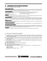
•The room where the heater is installed must have a good air flow to guarantee secondary air for the appliance for the combustion process and
for ventilation of the room. The natural air flow occurs directly through permanent apertures to the outside made in the walls of the room, or by
means of single or multiple ventilation ducting.
The ventilating air must come from outside and if possible, away from sources of pollution. Indirect ventilation is also allowed by taking in air from
rooms adjacent the one where the insert eater is installed taking into account all the warnings and limitations specified below.
•The apertures in the walls must comply with the following requirements:
- -have an unobstructed section of at least 6cm² for each Kw of installed thermal power, with a minimum limit of 100cm²;
- be made in such a way that the vent openings, both on the inside and outside of the wall, cannot be obstructed;
- be protected with grills or similar systems in order not to reduce the section described above;
- be situated at floor-level.
•The air flow can also be obtained from an adjacent room as long as:
- the adjacent room is equipped with direct ventilation in compliance with the points described above;
- in the room to be ventilated the installed appliances are only connected to one flue outlet;
- the adjacent room is not used as a bedroom or a common area of the building;
- the adjacent room is not a room with a fire hazard, such as storage sheds, garages, combustible material store rooms, etc...;
- the adjacent room does not become a vacuum compared to the room to be ventilated due to an opposite draught effect;
- the air flow from the adjacent room to the room to be ventilated is unobstructed through the permanent apertures having an overall net section
of no less than that indicated above. These apertures can be obtained by enlarging the space between the door and the floor.
This chapter is not intended to replace UNI 7129/92, UNI 10683 and EN 14785 standards to which it refers. The qualified
installer must in any case be fully aware of this standard and its amending versions.
8 . 4
8 . 4
8 . 4
8 . 4
8 . 4
B
B
B
B
BA
A
A
A
ATTER
TTER
TTER
TTER
TTERY REPLA
Y REPLA
Y REPLA
Y REPLA
Y REPLACEMENT FOR INFRARED REMO
CEMENT FOR INFRARED REMO
CEMENT FOR INFRARED REMO
CEMENT FOR INFRARED REMO
CEMENT FOR INFRARED REMOTE CONTR
TE CONTR
TE CONTR
TE CONTR
TE CONTROL.
OL.
OL.
OL.
OL.
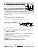
When the infrared remote control does not send out the transmission signal (led on), the battery must be replaced. Use a Phillips screwdriver
of proper size, to separate the half shells and replace the battery. The dead battery must be disposed of safely.
Inside the control panel there is a buffer battery type CR2032. When
hour and programming are not kept in storage , the battery must be
replaced using the 2 screws in the rear of the control panel. The
dead battery must be disposed of safely.
9
9
9
9
9
SMOKE DISCHARGE TUBE
SMOKE DISCHARGE TUBE
SMOKE DISCHARGE TUBE
SMOKE DISCHARGE TUBE
SMOKE DISCHARGE TUBE
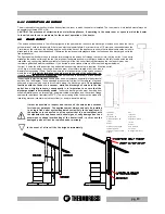
Due to the frequent accidents caused by poor functioning of flue outlets installed in private dwellings, we have prepared the following
paragraph to assist the installer in his inspection of the parts concerned with eliminating the gases produced by combustion. The gases
must be discharged in compliance with UNI7129/92, UNI 10683 and EN14785. 2006. It is necessary to accurately follow the directions
given below: Otherwise severe damages may occur for the product, the installation, objects and the people who use the generator.
The battery charger must be connected to a 220-240V 50Hz power mains. To obtain a total recharge of the batteries they must be charged for
at least 5 days: lower charge times could reduce the duration and life of the batteries. Leave the radio control connected at all times, by means
of the battery charger, to the power supply line. It is completely normal for symbols and/or lines to appear haphazardly on the display while the
battery is being charged. The optimal battery autonomy is achieved after several battery charge / discharge cycles.If the radio control is not used
for more than one week it is mandatory to switch it off completely in order to preserve the life of the batteries. Turn the switch located in the
battery compartment to 1, that is, OFF.
The batteries are guaranteed for 6 months.
Caution: Use only the battery charger provided by Thermorossi. The use of any other type of battery charger will invalidate the product
warranty.
17
13
As soon as the battery symbol on the display begins to blink, as shown in the drawing, the battery
needs to be charged.While it is being charged and consequently while it is connected to the electrical
power mains the battery symbol blinks continuously even when the batteries of the radio control are
completely charged.
This operation is necessary as otherwise the communication between the heater and the radio control
could be cut off. The batteries of the handheld radio control require regular recharging in relation to the
amount of use made of it The duration of the battery charge is variable and depends on how often the
remote control is used. The batteries must be recharged using the supplied battery charger :
INPUT 100V-240V 50/60 Hz 0,3/A OUTPUT 5,5V 750 ma
8.3
8.3
8.3
8.3
8.3
CHAR
CHAR
CHAR
CHAR
CHARGING
GING
GING
GING
GING THE B
THE B
THE B
THE B
THE BA
A
A
A
ATTER
TTER
TTER
TTER
TTERY OF
Y OF
Y OF
Y OF
Y OF THE HANDHELD RADIO CONTR
THE HANDHELD RADIO CONTR
THE HANDHELD RADIO CONTR
THE HANDHELD RADIO CONTR
THE HANDHELD RADIO CONTROL (optio-
OL (optio-
OL (optio-
OL (optio-
OL (optio-
nal)
nal)
nal)
nal)
nal)
BATTERIA TAMPONE CR2032
Buffer battery CR2032
8 . 5
8 . 5
8 . 5
8 . 5
8 . 5
R
R
R
R
Re
e
e
e
e placing the b
placing the b
placing the b
placing the b
placing the bu f
u f
u f
u f
u f fffffer ba
er ba
er ba
er ba
er batter
tter
tter
tter
tter y
y
y
y
y
o f
o f
o f
o f
o f the contr
the contr
the contr
the contr
the contr ol panel
ol panel
ol panel
ol panel
ol panel
Summary of Contents for ECOTHERM 5000
Page 16: ...pg 16 ...
Page 17: ...pg 17 ...


