pg. XIII
In order to guarantee correct absorption of the heat produced by the generator is it is advisable to use a boiler tube with volume and heat
exchange capacity suitable for the power of the generator.
4 . 6
4 . 6
4 . 6
4 . 6
4 . 6
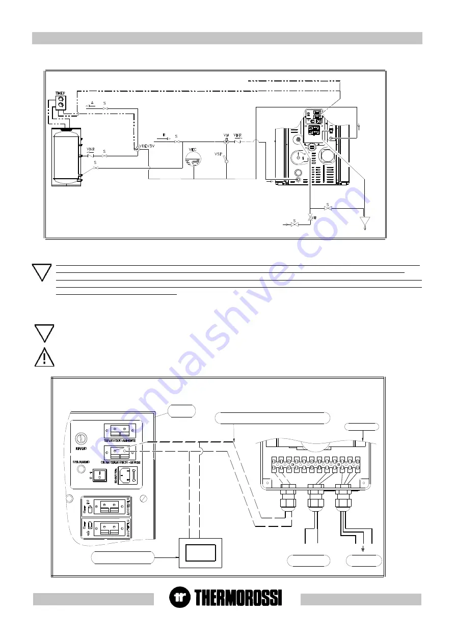
EXAMPLE OF HYDRA
EXAMPLE OF HYDRA
EXAMPLE OF HYDRA
EXAMPLE OF HYDRA
EXAMPLE OF HYDRAULIC DRA
ULIC DRA
ULIC DRA
ULIC DRA
ULIC DRAWING H
WING H
WING H
WING H
WING H
2
2
2
2
2
0/COMP
0/COMP
0/COMP
0/COMP
0/COMPA
A
A
A
ACT
CT
CT
CT
CT WITH BOILER COILS
WITH BOILER COILS
WITH BOILER COILS
WITH BOILER COILS
WITH BOILER COILS AND USE OF
AND USE OF
AND USE OF
AND USE OF
AND USE OF
THERMOCONTROL (OPTIONAL).
THERMOCONTROL (OPTIONAL).
THERMOCONTROL (OPTIONAL).
THERMOCONTROL (OPTIONAL).
THERMOCONTROL (OPTIONAL).
4 . 6 . 1
4 . 6 . 1
4 . 6 . 1
4 . 6 . 1
4 . 6 . 1 T
T
T
T
T her
her
her
her
her mocontr
mocontr
mocontr
mocontr
mocontr ol electrical connection w
ol electrical connection w
ol electrical connection w
ol electrical connection w
ol electrical connection w her
her
her
her
her e the H2O 25 / COMP
e the H2O 25 / COMP
e the H2O 25 / COMP
e the H2O 25 / COMP
e the H2O 25 / COMPA
A
A
A
ACT 25 boiler is inte
CT 25 boiler is inte
CT 25 boiler is inte
CT 25 boiler is inte
CT 25 boiler is inte g
g
g
g
g rrrrra
a
a
a
a ted
ted
ted
ted
ted
in a plumbing system with boiler coils.
in a plumbing system with boiler coils.
in a plumbing system with boiler coils.
in a plumbing system with boiler coils.
in a plumbing system with boiler coils.
The following is a description of the electric wiring for Thermocontrol and H2O 25 / Compact 25: through this electrical
connection, the shut off action by Thermocontrol automatically switches the diverter valve and also switches off the boiler: if the
system Chronothermostat requires more heat the boiler does not switch off until it has satisfied the heating requirements of the
room. The connections to the diverter valve and system chronothermostat are shown in the diagram and in the following photos.
CAUTION: in order to prevent too many boiler start ups, with consequent reduction in the electrical heater lifetime, the
manufacturer highly recommends using a chronothermostat with a thermal hysteresis of at least 2°C.
" CRONOTERMOSTATO - MODEM " sul pannello posteriore
ON / OFF ECOTHERM (da collegare al connettore
termica minima di 2°C).
Cronotermostato (con isteresi
Pannello
posteriore
Valvola deviatrice
220 V 50 Hz
N
F
220 V 50 Hz
Alimentazione
N
F
Thermocontrol
Caution: it is mandatory to earth the heater / boiler. If this instruction is not observed serious damage, which is not
covered by warranty, will result to the body of the heater / boiler. Have an electrician check the earthing. There
must be no electric potential (volts) between the earth of the generator and the actual earth of the plant. To prevent
electrochemical corrosion of the boiler body do not use galvanised pipes and fittings. Dedicated ground wires must
be used to ground all other materials .
See key page XLIII
TB : termostato bollitore
VR : valvola riduttrice di pressione
VM : valvola miscelatrice termostatica punto fisso 55°c.
VDEV3V : valvola deviatrice 3 vie
THER : thermocontrol
A : andata impianto riscaldamento
R : ritorno impianto riscaldamento
S : saracinesca
VNR : valvola di non ritorno
VEC : vaso di espansione chiuso per protezione impianto
VSP : valvola saracinesca ( da parzializzare in funzione
delle perdite di carico dell'impianto).
DAR
S C
CCI
CCT
A :
heating plant delivery
R:
heating plant return
S :
gate valve
VNR: nonreturn valve
VEC: closed expansion tank for plant protection
VSP: gate valve (throttle according to pressure drop in
the system )
VR:
reducing valve
T B :
reducing valve
VM:
thermostatic mixing valve, fixed point
55°C
VDEV3V: Three-way diverting valve
THER: Thermocontrol
CCI: system chronothermostat contact
CCT: chronothermostat modem contact
DAR: from water mains for make-up
SC:
outlet


