background image

Installation, use and maintenance guide 

PIDRA 18 


Page 

22


ENG 

1) Electrical power outlet 220V-240V 50Hz 
2) Main switch 0/I. 
3) Test light for pellet feed motor. 
The light comes on simultaneously with the activation of the pellet feed motor. 
4) Cap for reset thermostat button. 
If the reset thermostat overheats stop the pellet feeder. The appliance must cool down 
before you can restart the appliance. After verifying and eliminating the causes of the 
event, undo the protective cap and press the button. 
5) Protection fuse 3.15 A. 
6) Outlet RJ 45 to connect Wi-Fi module. 
 

6.3 DATE/TIME: SETTING THE DATE AND TIME 

The appliance must be energised and the I/0 switch in position “I". 
 
The current date and time can be set using the DATE/TIME function. 
 
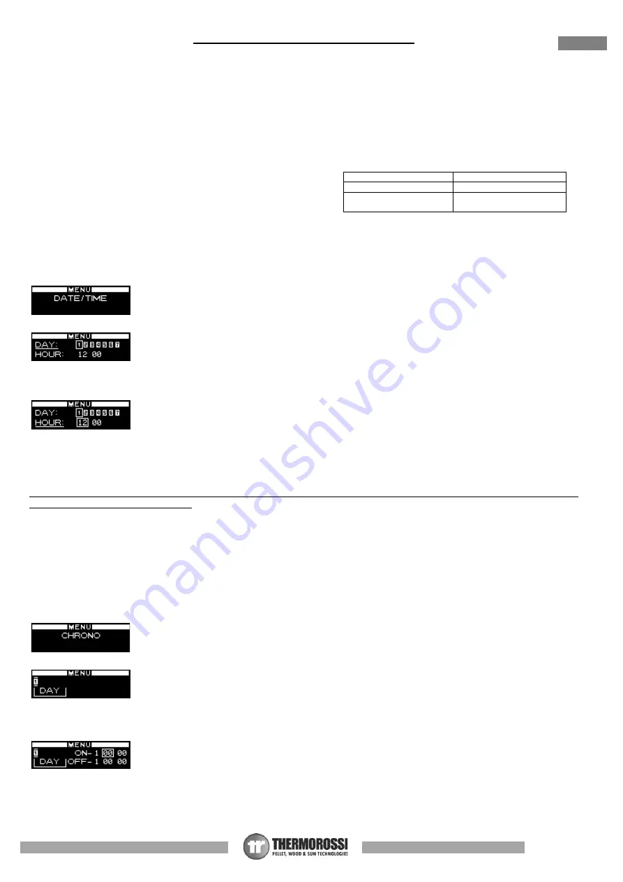
To set the current time and date proceed as follows: 


1)  Press the 

Menu Button 

once to view the


following screen:  


2)  After a few seconds the following screen will appear on the display: 


3)  Now  press  the 

Scroll  Buttons 

to  change  the  day  of  the  week;  each  number  corresponds  to  one  day  of  the  week  (e.g.  1 

corresponds to Monday, 2 corresponds to Tuesday, etc...).  To confirm the selected day of the week press the 

Degrees Button

Once confirmed, the selector shifts to the hour section while the selected day of the week remains framed:  


4)  Press the 

Scroll Buttons 

to change the hour. Once you have set the hour confirm the value by pressing the 

Degrees Button. 

Once confirmed, the selector shifts to the minutes section. Press the 

Scroll Buttons

 to set the minutes.  To confirm press the 

Degrees Button

Once confirmed, the date and time setting screen closes automatically and the initial screen returns to the display.  
 

If you confirm the wrong value simply press the 

Menu Button 

several times to exit the box until the initial screen will appear, and 

repeat the procedure described above. 
 

6.4 CHRONO: ON/OFF PROGRAMMING 

The appliance must be energised and the I/0 

switch in position “I". 

 
The CHRONO function allows you to set the weekly program by setting up to 3 on-off cycles at different times for every day from 
Monday through to Sunday. 
 
To set a program follow the procedure described below: 
1)  Press the 

Menu Button 

twice


quickly to view the following screen: 


After a few seconds the following screen will appear on the display: 


2)  Press the 

Scroll Buttons

 to select the day of the week on which you want to set the program. Each number corresponds to one 

day of the week (e.g. 1 corresponds to Monday, 2 corresponds to Tuesday, etc...). To confirm the selected day of the week for 
the programming press the 

Degrees Button

. The following screen will appear: 


3)  Now press the 

Scroll Buttons

 to select the hour at which you wish the appliance to start up automatically (ON1). Once the hour 

is set confirm the value by pressing the 

Degrees Button. 

When scrolling the ON1 values the OFF1 values will scroll as well; this 

is to avoid setting a shut off time that is earlier than the start up time.  
Once confirmed, the selector shifts to the minute section of ON1.  Press the 

Scroll Buttons

 to set the minutes for the first start 

up. Confirm by pressing the 

Degrees Button

Legenda 

Key 

RIARMO 

RESET 

SPIA MOTORIDUTTORE 

GEARMOTOR 
INDICATOR 

Summary of Contents for PIDRA 18

Page 1: ...PIDRA 18 INSTALLATION USE AND MAINTENANCE GUIDE Must read Important information for safety and correct operation ...

Page 2: ...Installation use and maintenance guide PIDRA 18 Page 1 ENG ...

Page 3: ...ERAL DESCRIPTION 9 4 INSTALLATION 11 5 HYDRAULIC CONNECTION 13 6 USE OF THE APPLIANCE 20 7 ROOM TEMPERATURE THERMOSTAT CHRONOTHERMOSTAT not supplied 34 8 CLEANING AND MAINTENANCE 36 9 SMOKE DISCHARGE TUBE AND VENTILATION OF THE ROOMS 42 10 ALARMS 46 11 ELECTRICAL WIRING 47 12 INFORMATION FOR THE SKILLED TECHNICIAN 49 ...

Page 4: ...lo n 4 36011 Arsiero VI 5 Nome e indirizzo del mandatario ai sensi dell articolo 12 paragrafo 2 Name and address of the agent as required pursuant Article 12 2 6 Sistema di valutazione e verifica della costanza della prestazione del prodotto da costruzione di cui all allegato V Sistema 3 e 4 System of assessment and verification of constancy of performance of the construction product as set out in...

Page 5: ...UE NL ENERGIE EFFICIENTIE INDEX DE ENERGIEEFFIZIENZINDEX ES ÍNDICE DE EFICIENCIA ENERGÉTICA 129 IT EFFICIENZA UTILE ALLA POTENZA TERMICA NOMINALE EN USEFUL ENERGY EFFICIENCY AT NOMINAL HEAT OUTPUT FR RENDEMENT UTILE À LA PUISSANCE THERMIQUE NOMINALE NL NUTTIG RENDEMENT BIJ NOMINAAL VERMOGEN DE BRENNSTOFF ENERGIEEFFIZIENZ BEI NENNWÄRMELEISTUNG ES EFICIENCIA ENERGÉTICA ÚTIL A POTENCIA CALORÍFICA NOM...

Page 6: ... by this symbol carefully as non observance of this message can cause serious injury to persons using the appliance DAMAGE TO PROPERTY This safety symbol identifies messages or instructions that are fundamental for the generator to function well To avoid serious damage to the appliance adhere strictly to these instructions INFORMATION This symbol indicates important instructions for good functioni...

Page 7: ...hen the appliance is cold and shut off Attention Warning for Swiss users Refer to the local cantonal regulations imposed by the Fire Department Mandatory signalling and safety distances and the Note concerning installation of heaters issued by the Association of Cantonal Fire Agencies VKF AEAI ATTENTION it is mandatory to earth the appliance If this instruction is not observed serious damage which...

Page 8: ...at rated power 95 60 Efficiency at reduced power 96 70 CO at 13 of 02 in the flue gases at rated power mg m3 52 0 CO at 13 of 02 in the flue gases at reduced power mg m3 215 0 Power supply voltage and frequency V Hz 230 50 Electrical consumption at rated power W 50 Electrical consumption at reduced power W 35 Electrical consumption in standby W 3 Loss of load water side at 10K mbar 128 Loss of loa...

Page 9: ...uito secondo i termini di legge in vigore ntonio Dal Molin 05 06 2020 dra 18 Scala Locazione file Data Firma Foglio te teriale dotto Sviluppo Assieme montaggio pidra 18 1 13 TEL 0445 741310 FAX 0445 741657 Via Grumolo 4 36011 ARSIERO Vicenza ITALY S p A essore Approv Data approv Formato 0030186 d egnatore Volume Peso Colore Revisione 543 781 kg 237223277 16 mm 3 tr dc01 DatiOffice Reparti Tecnico ...

Page 10: ...TTENTION it is normal to find some pellets remaining in the tank even if the stove shuts off because the pellets have run out Attention when filling up the tank take care not to drop any pellets into the internal parts of the appliance as in extreme cases this could generate live flames The manufacturer recommends emptying the tank and vacuuming the screw feeder zone once a month and during the su...

Page 11: ...be scraper lever E Combustion air intake T Power board F Safety pressure switch U Combustion chamber Patented burner G Manual reset button V Handle H Pellet loading motor W boiler drain refill tap I Tank pellet X Plant water return J Main switch 0 I Y Safety valve 3 bar 1 2 K Plant water delivery AC 2 l closed expansion tank for generator protection L Electronic board AD Smoke thermocouple N Light...

Page 12: ...n will immediately invalidate the warranty The installer must issue a certificate of conformity for the installation which includes the design plans and the following documents a Report containing the type of materials utilised b Project as defined in Article 5 of Ministerial Decree n 37 22 January 2008 d References to existing partial or previous declarations of conformity e g electrical wiring e...

Page 13: ... would certainly damage the control panel damage which is not covered by warranty 4 5 HANDLE Your appliance is supplied with a handle for opening and closing the firebox door to facilitate cleaning see dedicated paragraph When not in use the handle can be stowed on the rear of the appliance 4 6 DRAWING COMBUSTION AIR FROM OUTSIDE The appliance is fitted with an intake to enable drawing in the comb...

Page 14: ... ATTENTION A CONNECTION MUST BE MADE BETWEEN THE SAFETY VALVE AND THE OUTLET TO PREVENT DAMAGING MATERIALS SURROUNDING THE APPLIANCE WHEN THE VALVE IS ACTIVATED ATTENTION To avoid continual startups and shut offs the size of the plant must be such as to guarantee power absorption that is not less than the power generated by the generator running at minimum steady state power level 1 System circula...

Page 15: ...at contact closed automatically activates the generator In the event of frequent startups and shut offs due to the heat produced by the generator not being absorbed the manual reset safety thermostat trips and blocks the generator N B Use chronothermostats having at least 2 C hysterisis Legenda Key Elettrovalvola sempre aperta zona con più assorbimento Solenoid valve always open zone with the most...

Page 16: ... the generator If this instruction is not observed serious damage which is not covered by warranty will result to the body of the appliance Have a skilled electrician check the earthing There must be no electric potential Volt between the generator earth and the system s real earth earth plate To prevent electrochemical corrosion of the appliance body do not use galvanised pipes and fittings Other...

Page 17: ...ture that is the temperature set in the generator The boiler tubes can be installed on the water return circuit It is recommended to install a water softener in the domestic water system in order to maintain the boiler at its peak efficiency ATTENTION it is mandatory to earth the generator If this instruction is not observed serious damage which is not covered by warranty will result to the body o...

Page 18: ...e it supplies power to pin 7 Consequently the system must be designed in such a way that the hot water produced by the generator can reach the various rooms by acting on the zone valves ATTENTION it is mandatory to earth the generator If this instruction is not observed serious damage which is not covered by warranty will result to the body of the appliance Have a skilled electrician check the ear...

Page 19: ...r S2 board Sensor S2 must always be positioned at the same height as the water delivery to the system ATTENTION Sensor S1 must be set at a range of between 60 C and 65 C sensor S2 must be set at a range of between 50 C and 55 C These settings are only approximate as the optimal setting is carried out by the Service Centre on site during the initial testing of the appliance following the assessment...

Page 20: ...nerator when the water reaches the temperature setting The system starts up again automatically when the water temperature drops below the preset value d a manual reset temperature limiting safety device this is an automatic device that interrupts the fuel supply when the water reaches the maximum permissible temperature The fuel infeed will only restart when the water temperature drops below a pr...

Page 21: ...he main feature of the panel is the all automatic management of the appliance The controls and the various displays are described below Flame button Pressing this button when the appliance is off activates the START sequence sets the operating power in the WORK mode or shuts off the appliance by activating the OFF sequence See dedicated paragraph Degrees Button Press this button to set the target ...

Page 22: ...ragraph Indicates the temperature of the domestic hot water boiler if the optional sensor is connected Indicates the temperature of Sensor S1 for control of a puffer if the optional sensor is connected Indicates the temperature of Sensor S2 for control of a puffer if the optional sensor is connected Indicates that the circulation pump is activated when the water temperature in the boiler exceeds 6...

Page 23: ... set the minutes To confirm press the Degrees Button Once confirmed the date and time setting screen closes automatically and the initial screen returns to the display If you confirm the wrong value simply press the Menu Button several times to exit the box until the initial screen will appear and repeat the procedure described above 6 4 CHRONO ON OFF PROGRAMMING The appliance must be energised an...

Page 24: ...by pressing the Degrees Button At this point the second ON OFF cycle for the selected day has been set The following screen will appear At this point if no further programming is required for that day go to point 6 A If on the other hand you wish to program a third ON OFF cycle for that day go to point 6 B 6 A Press the Menu Button to exit the screen in order to enable you to program the times for...

Page 25: ...rily on the screen Do not release the button until the text CLEARED appears on the screen Only the appearance of the words CLEARED signal that the previously entered programmed cycles have been deleted When the programmed cycles are active the operating level at start up that is the combustion power will be the same level set before the last time the machine was shut off that is only if it was a p...

Page 26: ...ic board see dedicated paragraph ATTENTION If one or both optional sensors are not connected to the appliance or are interrupted it will not be possible to view and therefore activate the THERMOCONTROL function When this function is activated the appliance automatically controls the ON OFF cycles based on the activation temperatures set by the user The puffer must have an appropriate capacity We r...

Page 27: ... the temperatures detected by the sensors S1 and S2 and the word PUF will appear on the display When is it important to use the THERMOCONTROL function In systems configured like the diagram on the right where the appliance is connected directly to a stratification puffer When you use this function the generator starts up automatically when the puffer is running out of heat then switches off when i...

Page 28: ...hower symbol will appear and next to it the temperature detected by the sensor To deactivate ACS SUMMER function simply repeat operations 1 and 2 in this paragraph but this time select the OFF command The function will be disabled immediately ATTENTION If the optional sensor is not connected to the appliance or is interrupted it will not be possible to activate this function ATTENTION The boiler t...

Page 29: ...appliance or if it is interrupted it will not be possible to activate this function Pay special attention to the number of ON OFF cycles that the appliance is subjected to with this function It is recommended not to exceed three ON OFF cycles If the startups are frequent and repeated it is possible that the generator will fail to start and the following error message appear Failed start Clean burn...

Page 30: ...s installed in the central part of the boiler tube and commands the appliance to start the boiler if it is off On the other hand if the appliance is operating it commands the diverting valve as the available heat inside it is coming to an end The setting range is from 45 C to 65 C 5 Confirm the selection by pressing the Degrees Button and the following screen will appear 6 Press the Scroll Buttons...

Page 31: ... use the THERMO ACS function In systems configured like the nearby diagram where the appliance is connected directly to a domestic hot water boiler tube and to the system When using this function the generator starts up automatically when the boiler tube is running out of heat Once the boiler tube is satisfied the appliance switches the 3 way valve to provide heat to the system We recommend instal...

Page 32: ... the generator to begin a new START phase only when the temperature drops below 58 C ATTENTION The STOP mode must be considered an overtemperature pre allarm and therefore cannot be considered a normal operating stage WAIT ON when the appliance is restarted while hot where the water temperature is higher than 63 C the appliance does not start immediately but the circulating pump will still be acti...

Page 33: ... finding the correct temperature in order to optimise the full potential of the produced heat If the value is set at a high temperature let s say 73 C the appliance will attempt to reach that level as quickly as possible by modulating the power as it approaches the set temperature It is not necessary to set high t max temperatures when the ambient conditions do not require them Time and experience...

Page 34: ...up and suction values preset by the Manufacturer The electrical heater will start to overheat and only after a few minutes the first lot of pellets will start dropping into the brazier This occurs because the screw feeder has to fill up because it is completely empty At the first start up the appliance may require the starting sequence to be performed twice for the reason explained above before st...

Page 35: ...erature the room thermostat closes the contact the appliance will operate at the minimum combustion power and the 1st power bar will flash on the display any manual power change will be disabled When the room temperature drops the thermostat opens the contact and the appliance returns to its original position in terms of thermal power ATTENTION N C Normally Closed contacts must be used for the con...

Page 36: ... nearby diagram where the appliance is connected directly to the system In this case the chronothermostat controls the ON OFF cycles of the appliance according to the programmed time bands or the temperature setting If the dwelling is fitted with zone valves with this type of installation it is mandatory to deactivate the valves by opening them completely Consequently the dissipation of heat at le...

Page 37: ...horoughly clean the burner Figure 1 with a vacuum cleaner carefully clean the area around the spark plug This is to ensure that the appliance operates correctly and to avoid start up failures Move the tube scraper lever up and down vigorously at least 4 5 times Figure 2 EVERY WEEK Open the firebox door and check that the area where the Pelletpower scraper works is sediment free Figure 1 Check that...

Page 38: ...hannel and flue outlet must be cleaned in accordance with the specifications described above and use of inflammable products is strictly forbidden using inflammable products can create dangerous situations Failure to carry out the necessary maintenance or if only partial maintenance is carried out will affect the correct functioning of the appliance Any problems resulting from total or partial lac...

Page 39: ...Installation use and maintenance guide PIDRA 18 Page 38 ENG C DETTAGLIO C FIGURE 1 FIGURE 2 DETAIL c ...

Page 40: ...Installation use and maintenance guide PIDRA 18 Page 39 ENG C1 C2 FIGURE 3 FIGURE 4 ...

Page 41: ...Installation use and maintenance guide PIDRA 18 Page 40 ENG D DETTAGLIO D C3 C3 FIGURE 5 FIGURE 6 DETAIL D DETAIL c B DETTAGLIO B ...

Page 42: ...Installation use and maintenance guide PIDRA 18 Page 41 ENG FIGURE 7 ...

Page 43: ...w can also be obtained from an adjoining room as long as the adjoining room is equipped with direct ventilation in compliance with the paragraphs described above only appliances connected to the exhaust pipe are installed in the room that is ventilated the adjoining room is not used as a bedroom or a common area of the building the adjacent room is not a room with a fire hazard such as storage she...

Page 44: ... using a combination of compatible components such as flue liner wall directly in contact with the smoke and possibly also insulation and outer casing wall that may be supplied by different manufacturers or by the same manufacturer Relining operation involving the installation of a specific pipe in an existing shaft even if newly constructed made of non combustible materials free from obstructions...

Page 45: ...decide to use the classic masonry exhaust provide a union tee with inspection cap and suitable supporting brackets If the flue outlet is too big it is necessary to insert a stainless steel or porcelain coated steel tube with a diameter not exceeding 150mm Seal area where the inlet and outlet part of the smoke exhaust meets the wall It is strictly forbidden to apply mesh to the end of the outlet tu...

Page 46: ...able to provide a condensation drain near the smoke outlet of the appliance The appliance must always and only be installed in a single flue outlet system dedicated exclusively to the appliance If the generator is connected to a non compliant flue system the appliance could rapidly deteriorate due to an abnormal continuous overheating in this case the damaged parts will not be covered by warranty ...

Page 47: ...d off then on by turning the switch 0 1 located on the power panel Before restarting the appliance check for any irregularities such as blocked flue outlet open firebox door Do not start up the appliance until the problem has been identified and solved It is mandatory to empty and clean the brazier before repeating the START phase This appears when the water temperature in the appliance exceeds 95...

Page 48: ...a riproduzione totale e o parziale e la divulgazione a terzi senza nostro esplicito consenso scritto verrà perseguito secondo i termini di legge in vigore Scala Locazione file Data Firma Foglio Note Materiale Prodotto Sviluppo 22 22 TEL 0445 741310 FAX 0445 741657 Via Grumolo 4 36011 ARSIERO Vicenza ITALY S p A Spessore Approv Data approv Formato viste Cod Disegnatore Volume Peso Colore Revisione ...

Page 49: ...ressostato Motoriduttore caricamento pellet Spia Verde L2 L1 N LEGENDA KEY optional optional Sonda PT 100 Generatore Sensor PT 100 Generator Sonda PT 100 ACS Sensor PT 100 Domestic hot water ACS Sonda PT 100 S2 Sensor PT 100 S2 Sonda PT 100 S1 o TAMBIENT Sensor PT 100 S1 or TAMBIENT Morsettiera CN5 Terminal block CN5 Modem Modem Termostato ambiente Room temperature thermostat Morsettiera CN7 Termi...

Page 50: ...erature reactivate the appliance by unscrewing the plastic cover of the thermostat and press the button the temperature of the appliance must have dropped considerably SPARK PLUG It is activated in the START phase It heats the incoming air to the brazier up to 800 C which promotes the first combustion of the pellets in the brazier AUTOMATIC PURGE VALVE The function of this valve is to eliminate ai...

Page 51: ...ld obviously cause the appliance to malfunction Keep the appliance clean and check the burner as described in these instructions Clean the smoke outlet regularly Use good quality pellets use of poor pellets can result in up to 50 less efficiency The pellets must be stored in a well ventilated dry place The generator door must always remain closed during normal operation Do not touch hot outer surf...

Page 52: ...KED RUN THE APPLIANCE AT HIGH POWER LEVELS FOR A FEW DAYS THE SMOKE EXHAUST IS NOT SEALED CORRECTLY CHECK THE TIGHTNESS OF THE FLUE OUTLET PARTICULARLY THE CONDITION OF THE EXHASUT PIPES AND THE TIGHTNESS OF THE SEALS IF SMOKE BEGINS TO LEAK FROM THE APPLIANCE TOWARDS THE END OF THE STARTUP SEQUENCE DIRTY BRAZIER STARTUP SUCCESSFUL BUT WITH CONSIDERABLE DELAY CLEAN THE BRAZIER AS INDICATED IN THIS...

Page 53: ...TTON TO ENABLE IT AS INSTRUCTED IN THIS USE AND MAINTENANCE GUIDE THE BUFFER BATTERY INSTALLED IN THE CONTROL PANEL FACEPLATE IS DEAD CONTACT THE TECHNICAL ASSISTANCE SERVICE FOR REPLACEMENT OF THE BATTERY AN INCORRECT PROGRAMMING PROCEDURE WAS CARRIED OUT VERIFY THE TIMES SET IN THE CHRONO FUNCTION THE BRAZIER CLEANING MECHANISM IS WORN POOR QUALITY PELLETS CONTAINING CHEMICAL BINDERS CHANGE TO A...

Page 54: ...Installation use and maintenance guide PIDRA 18 Page 53 ENG Via Grumolo 4 Z I 36011 Arsiero VI ITALY Fax 0445 741657 www thermorossi com info thermorossi it F ireL o v e rs Code 70030743 11 2020 ...

Reviews: