Page 21
Installation, use and maintenance guide
SlimQuadro Idra 14
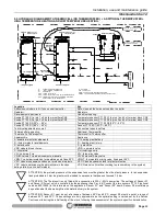
5.4 EXAMPLE OF HYDRAULIC DIAGRAM WITH BOILER COILS AND HEATING SYSTEM
Legenda
Key
Contatto cronotermostato
Chronothermostat contact
Impianto
System
Contatto cronotermostato modem della caldaia
Chronothermostat modem contact of the stove
SB ai pin 5 e 6 della morsettiera CN5
SB to pins 5 and 6 of the terminal block CN5
Alimentazione dalla morsettiera CN3 pin 5 (neutro), pin 7 (L1), pin 8
(L2)
Power supply from the terminal block CN3 pin 5 (neutral), pin 7 (L1),
pin 8 (L2)
Scarico
Outlet
APPARECCHIO
APPLIANCE
A: andata impianto riscaldamento
A – heating plant delivery
R: ritorno impianto riscaldamento
R – heating plant return
S: saracinesca
S – gate valve
VNR: valvola di non ritorno
VNR – nonreturn valve
VEC: vaso di espansione chiuso per protezione impianto
VEC: closed expansion tank for plant protection
VSP: valvola saracinesca (da parzializzare in funzione delle perdite
di carico dell’impianto)
VSP: Gate valve (throttle according to pressure drop in the system)
SB: sonda acqua calda sanitaria
SB: domestic hot water sensor
VR: valvola riduttrice di pressione
VR: pressure reducing valve
VM3VT: valvola miscelatrice termostatica punto fisso 55°C
VM3VT: thermostatic mixing valve, fixed point 55°C
VDEV3V: valvola deviatrice 3 vie alimentata in chiusura e anche in
apertura
VDEV3V: 3 way diverting valve powered at closure and also at
opening
Dall’acquedotto per reintegro
From water mains for make-up
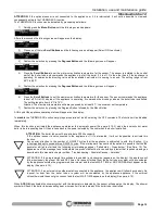
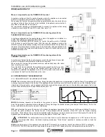
In order to guarantee correct absorption of the heat produced by the generator it is advisable to use a boiler tube with volume and
heat exchange capacity suitable for the power of the generator. The boiler tube must have a minimum capacity of 300l. In any case
the boiler tube must be capable of absorbing all the power that the generator is capable of delivering.
If this rule is not observed, the generator could raise the water temperature to such a point as to activate the safety limit thermostat
which stops the fuel from dropping into the burner and therefore forces the appliance to shut off.
The installer is required to install a valve that switches over to the system, powered by the stove’s control unit, which trips when the
boiler is thermally “satisfied ”. Consequently, the plant must be designed in such a way that the hot water produced by the generator
can reach the various rooms by acting on the zone valves.
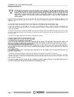
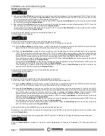
ATTENTION: it is mandatory to earth the generator. If this instruction is not observed serious damage, which
is not covered by warranty, will result to the body of the appliance. Have a skilled electrician check the
earthing. There must be no electric potential (Volt) between the generator earth and the plant’s real earth
(earth plate). To prevent electrochemical corrosion of the appliance body do not use galvanised pipes and
fittings. Other materials must be earthed with special earthing cables in order to obtain a unipotential
earthing system.
S
R
S
VN R
S
VN R
S
A
VDEV3 V
VEC
VM3 VT
Co n t a t t o Cr o n o t e r m o s t a t o
Mo d e m d e l l a c a l d a i a
Co n t a t t o Cr o n o t e r m o s t a t oIm p i a n t o
V SP
p e r r e i n t e g r o
Da l l ' a c q u e d o t t o
s c a r i c o
S
VR
A
P
P
A
R
E
C
C
H
IO
A
R
A : andata impianto riscaldamento
R : ritorno impianto riscaldamento
S : saracinesca
VNR : valvola di non ritorno
VEC : vaso di espansione chiuso per protezione impianto
VSP : valvola saracinesca ( da parzializzare in funzione
delle perdite di carico dell'impianto).
SB : sonda acqua calda sanitaria
VR : valvola riduttrice di pressione
VM3VT : valvola miscelatrice termostatica punto fisso 55°c.
VDEV3V : valvola deviatrice 3 vie alimentata in chiusura e anche in apertura.
Alimentazione dalla morsettiera CN3
pin 5 (neutro), pin 7 (L1) , pin 8 (L2)
SB ai pin 5 e 6 della
morsettiera CN5.


