T9901085-1-3 UK
Page 20 of 38
COMMISSIONING THE AIR CURTAIN
Ensure that the electrical supply to the Mitsubishi Electric Outdoor Unit and, if
applicable, the 3-phase local electrical supply to the Air Curtain, are switched off.
Air Curtain Checks
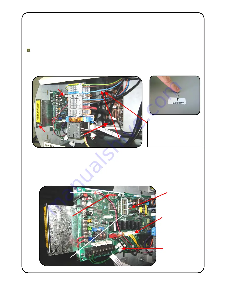
Check that the components inside the air curtain are as shown in the picture below. If
the defrost cycle auxiliary heater has been enabled check that the thermal overheat cut-
out switch(s) has not ‘tripped’. Press the reset button at the top of the unit (2 on a
HP2000 DXE unit). If the cut-out switch has tripped it will click back on – see picture
There is a Mitsubishi Electric Interface PCB located within the left hand end of the
Thermoscreens Air Curtain. This provides control and communication between the
Mitsubishi Electric Outdoor Unit and the Air Curtain Indoor Unit. It is held in place by a
fixing screw located in the left-hand end panel of the air curtain under the left-hand
plastic end cap. Remove the screw and carefully slide the PCB partially out. For easier
withdrawal of the PCB the filter indicator connection may be temporarily removed.
Shown set up for Weather
Compensation/Discharge Air
Temperature Control. See
Page 21 to see set-up for
Inlet Air/Room Air
Temperature Control.
Discharge Air temperature
Sensor
RED
Interface PCB
Liquid Line
Sensor
WHITE
TOP OF UNIT
PCB fixing
screw
DIP SWITCHES
LED 1
Un-plug green
plug CNX5 for
cooling mode
with Inlet Air or
Room Air Temp.
Control
Filter Indicator
Connection
LEDs 2-5
Condensate
Pump Alarm
Connection


