background image

11   


RUN


M

ODE   

O

PERATING   

P

ROCEDURES


5

When   the   T257P   Chiller   is   operating   and   providing   temperature   controlled   fluid   it   is   said   to   be   in   the   
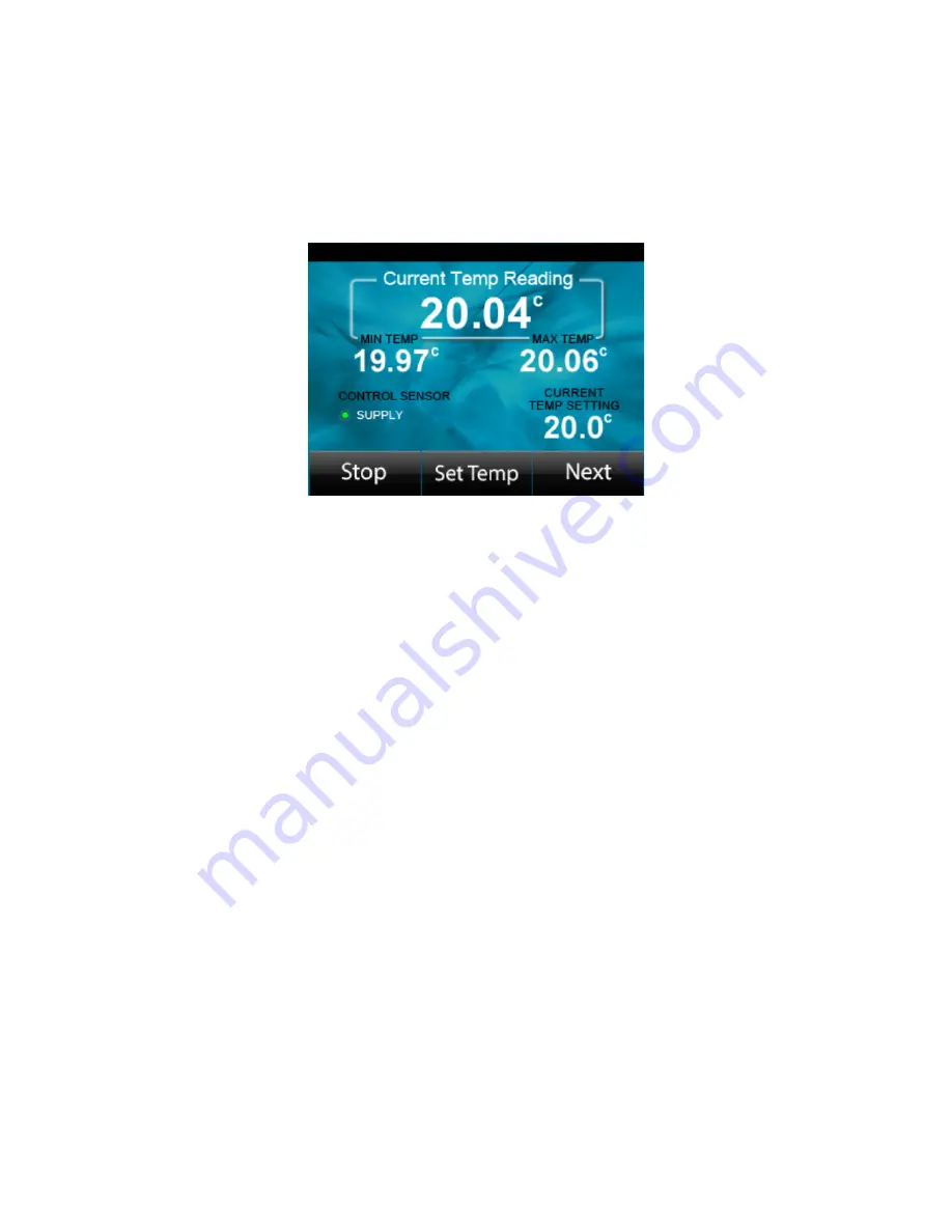
RUN   Mode.      During   the   RUN   Mode   the   screen   content   shown   in   figure   5-­‐1   is   displayed.         The   RUN   
Mode   screen   shows   the   instantaneous   fluid   temperature,   the   maximum   and   minimum   temperature   
stability    over    the    past    60    minutes,    the    set    temperate;    the    sensor    used    to    control    the    fluid    and    if   
applicable,   the   coolant   flow   rate.   


Figure   5-­‐1:   RUN   Mode   Screen   


While   in   the   RUN   Mode   the   following   features   are   accessible:   


Set   the   device   in   STANDBY   Mode   


Set   /   Change   control   temperature   


Set   /   Change   pump   speed   (if   applicable)   


Set   /   Change   user   specified   temperature   alarms   


Access   the   Monitor   screen   for   detailed   operational   status   


How   to   Stop   and   Start   the   T257P   Chiller   

5.1

1.


To   stop   the   T257P   Chiller,   press   the   “Stop”   button.      This   will   place   the   system   in   standby   mode   
with   the   coolant   pump   and   the   temperature   control   subsystem   in   idle   state.   

2.


The    fans    will    continue    to    operate    for    some    time    to    cool    the    heat    sinks.        Once    the    heat    sink   
temperature   is   near   ambient   the   fans   will   enter   the   idle   state.   

3.


To    Start    the    T257P    Chiller,    press    the    “Start”    button.        This    will    display    the    RUN    Mode    screen   
with   the   chiller   controlling   the   fluid   to   the   previous   set   temperature.   
   

Summary of Contents for T257P

Page 1: ...T257P Precision Chiller User Manual...

Page 2: ...1 How to Change the Set Temperature 12 5 2 How to Change the User Specified Temperature Alarm Limits 13 5 3 How to Change the Pump Drive for applicable configurations 14 5 4 How to Access the Monitor...

Page 3: ...5 9 Technical Specifications 26 10 T257P System Technical Specification 26 10 1 T257P System Performance 27 10 2 T257P Communication Protocol 28 10 3 T257P System Wetted Path Materials 29 10 4 T257P S...

Page 4: ...1 If you have questions about the T257P system or require service please contact ThermoTek Inc at 1200 Lakeside Parkway 200 Flower Mound TX 75028 Tel 972 874 4949 8 00am 5 00 pm CT Explanation of Symb...

Page 5: ...y and or damage to the product and will void any warranty Do not spill liquids of any kind on T257P system Always use the T257P system with a grounded power inlet Do not use the T257P system with powe...

Page 6: ...impact to the T257P device Do not operate the T257P device if it is damaged or leaking fluids Do not operate the T257P device beyond its rated capacity Do not operate the T257P device outdoors Do not...

Page 7: ...culating fluid The heat removed from the application is rejected to the environment via the heat transfer system housed within the device Features 3 1 Lightweight portable system Ergonomic easy to car...

Page 8: ...8 Device Illustration 3 2...

Page 9: ...e power cord into the unit 9 Plug the male end into the AC voltage outlet within the device specified voltage Please refer to the technical information section for input voltage specifications Startup...

Page 10: ...ating and controlling to set temperature the RUN Mode screen content will be displayed on the LCD screen Note If the application is located above the chiller there is a potential for the fluid to over...

Page 11: ...le Set the device in STANDBY Mode Set Change control temperature Set Change pump speed if applicable Set Change user specified temperature alarms Access the Monitor screen for detailed operational sta...

Page 12: ...ttons are pressed the temperature setting will initially change in 0 1C increments If the key is held down for more then 5 seconds the temperature will change in 1 0C increments To go back to 0 1C ste...

Page 13: ...its 4 Press the UP or DOWN arrow to change the temperature to a new setting The new setting will be shown on the right under New 5 Once the correct alarm temperature is selected press the Accept butto...

Page 14: ...ted press the Accept button to confirm change to the set temperature 7 If the Cancel button is pressed the new changes are canceled and the previous pump drive will stay active 8 Pressing the Accept o...

Page 15: ...een as shown in figure 5 6 displays the internal system control parameters of the T257P system From this one can view all the available temperatures TEC drive levels pump and fan states to aid in the...

Page 16: ...Standby Mode Options How to Set the Control Mode 6 1 The control mode has been optimized to provide temperature stability from a minimum flow rate of 0 75 to 3 5 lpm Currently only one control mode i...

Page 17: ...on Screen Note 1 At present only the supply sensor option is available The remote sensor operation is a planned future update to the product How to Set the COM Port 6 3 1 T257P Systems are equipped wi...

Page 18: ...utton 3 This will navigate to the Set Fan drive screen The screen will show the current and the new Fan drive 4 Press the UP or DOWN arrow to change the fan drive to a new setting The new drive settin...

Page 19: ...ode screen press the Next button twice 3 On the following screen Press the Alarm History button 4 After reviewing the alarm history press the Accept button to return to the Standby Mode screen System...

Page 20: ...ectors on one side and open tube on the other to the supply and return ports and drain the fluid into a discard vessel 4 Turn on the unit and set the unit in Run Mode 5 Keep adding fresh fluid of 500...

Page 21: ...and mild household cleaner and wipe all exterior surfaces 3 Use a dry static free cloth to clean the display window 4 Let the T257P system dry completely before powering on the system Cleaning the He...

Page 22: ...tem follow these steps 1 Power down the T257P system and unplug the AC power cord 2 Drain all fluid from the T257P system by following section 7 2 steps 1 6 3 Replace the Reservoir cap 4 Package the T...

Page 23: ...alarm When this alarm is active the device is stopped and will require user intervention to determine and resolve the cause of the alarm and once cleared restart the device High Ambient Temp Alarm If...

Page 24: ...s alarm is active the device is stopped This alarm indicates there is a potential failure of the supply temp sensor Turn off power to the device for 60 seconds Power up the device and if the alarm re...

Page 25: ...Valved Flow Barb Acetal 0P2E100412 CPC Quick Disconnect Female Valved M NPT Acetal QD on unit 0P2ES17006 CPC Quick Disconnect Male Non Valved Flow 3 8 Barb Aceral 0P2ES17004 CPC Quick Disconnect Male...

Page 26: ...pacity 225 Watts with control set point at ambient temperature Device Pumping Capacity Pump Option 1 3 5 LPM Open Flow 12 psi Max Pressure 0 Flow Pump Option 2 3 5 LPM Open Flow 20 psi 0 flow Temperat...

Page 27: ...27 T257P System Performance 10 2 Note...

Page 28: ...applications may affect chiller performance Consult ThermoTek for application assistance 6 Specification subject to change without notice T257P Communication Protocol 10 3 The T257P Communication prot...

Page 29: ...System Guidance and Manufacture s Declaration Electromagnetic 10 6 Emissions This device has been tested and found to comply with the limits for Electrical equipment for measurement control and labora...

Page 30: ...uipment into an outlet or circuit different from the one where the other device s are connected Connect an external 20 AWG ground wire from the eqi potential ground tab on the right side of the chille...

Page 31: ...ectiveness or intended use voids the warranty ThermoTek will at its option repair or replace within a reasonable time any product that is found to have a defect in material or workmanship under normal...

Page 32: ...and remedy against thermotek regardless of whether such claims are based on warranty contract tort or any other theory ThermoTek Disclaims and is not responsible for direct special incidental consequ...

Page 33: ...33...

Page 34: ...34 1200 Lakeside Parkway 200 Flower Mound TX 75028 Website www thermotekusa com Tel 001 972 874 4949 PN 0P1D257MEN Rev X1 08 2016 0P1D257MEN X1...

Reviews: