background image


13


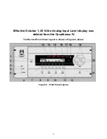
Effective October 1, 2014 the Analog Input Level display was 

 deleted from the Casablanca IV.   


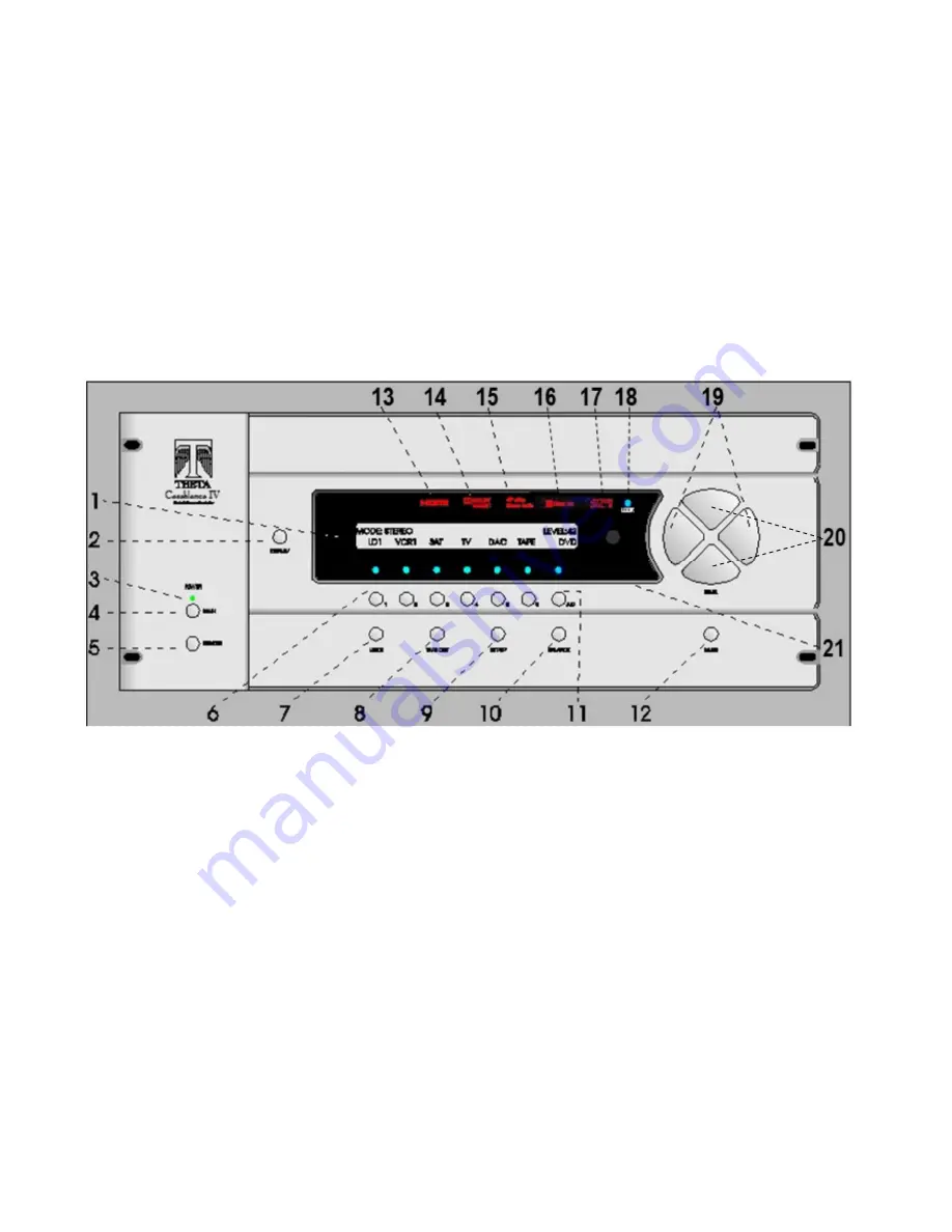
The Revised Front Panel Layout is shown in Figure 6, below.   


Figure 6 - Front Panel Layout 


Summary of Contents for Casablanca IV

Page 1: ...13 Effective October 1 2014 the Analog Input Level display was deleted from the Casablanca IV The Revised Front Panel Layout is shown in Figure 6 below Figure 6 Front Panel Layout...

Page 2: ...THETA DIGITAL Casablanca IV Owner s Manual V 4 02 Digital Done Right...

Page 3: ...se harmful interference to radio communications However there is no guarantee that interference will not occur in a particular installation If this equipment does cause harmful interference to radio a...

Page 4: ...xclamation point within an equilateral triangle is intended to alert the user to the presence of important operating and maintenance servicing instructions in the literature accompanying the product W...

Page 5: ...stalled Whenever upgrades inquiries and or changes are requested the serial number will be required SERIAL NUMBER DATE PURCHASED DEALER S NAME DEALER S ADDRESS PHONE INSTALLED CARDS OPTIONS Date of in...

Page 6: ...VENTILATION SPACE ABOVE THE UNIT IMPROPER VENTILATION OF THE UNIT MAY CAUSE OVERHEATING WHICH MAY DAMAGE THE UNIT AND CAUSE A FIRE PLACE THE UNIT ON A SOLID SURFACE ONLY I E NOT ON CARPET ETC DO NOT...

Page 7: ...nput Select Pages 42 Selecting Mapped Input Jacks for the Currently Selected Input 42 Search Order 44 MODE Function 45 TAPE OUT Function 48 SETUP Function 49 DAC Configuration 49 SETUP INPUT Settings...

Page 8: ...s and unique testing procedure that insures that it will last for many years with minimal service requirements This procedure includes the following All assembled circuit boards are given a thorough v...

Page 9: ...asablanca IV is placed in a well ventilated area or rack unit V Please take note that some powerline conditioners defeat the AC power ground on their outlets If the intention is to plug the Casablanca...

Page 10: ...Converter A device that converts digital signals into an analog format Hz Hertz A unit of frequency IR Infrared A method of wireless transmission of data Jitter Jail II A technology proprietary to Th...

Page 11: ...10 Casablanca IV Block Diagram Input Processing Sections Figure 1 Input processing block diagram...

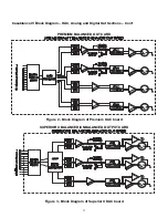
Page 12: ...Block Diagram DAC Analog and Digital Out Sections Con t PREMIUM BALANCED OUT CARD Figure 2 Block Diagram of Premium DAC board SUPERIOR II BALANCED UNBALANCED OUTPUT CARD Figure 3 Block Diagram of Supe...

Page 13: ...agram of Xtreme D 2 4 Channel DAC board Figure 5 Block Diagram of Digital Output board showing all options Note Digital Output Card is normally supplied with 6 XLR outputs 6 S PDIF outputs are availab...

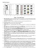
Page 14: ...button Sets temporary speaker balance configurations and analog input levels to compensate for different program characteristics 11 A D button Sequences through input jacks mapped assigned to the act...

Page 15: ...An externally mounted remote Infrared IR receiver plugs into this miniature stereo phone jack Its signal must be demodulated Please refer to Appendix C on page 89 for additional information 9 Power S...

Page 16: ...cally contain outputs for sub left surround and right surround channels 16 Third Analog Output card This slot could contain one of the following options A four channel Xtreme D 2 quality DAC a four ch...

Page 17: ...16 Figure 8 All Superior II D A Card Options...

Page 18: ...Surround Back Left Right Surround Back Left Right Surround Left Right Front Left Right Center Sub 1 Sub 1 Sub 2 Sub 3 or Sub 5 Surround Back Left Right Sub 5 Sub 1 Surround Back Left Right or Sub 5 Su...

Page 19: ...18 Menu Maps Function Menus and Pages Figure 10 Mode Status Tape Out Menus and Input Select Pages...

Page 20: ...19...

Page 21: ...tons will adjust the master volume An exception to this is the first BALANCE page and the pages where input select buttons and input jacks are named In a few cases simply pressing the 1 6 buttons make...

Page 22: ...21...

Page 23: ...I3 6 DVDA HDMI4 7 SACD TOS2 8 TUNR COAX2 9 SAT COAX3 10 CABL TOS1 11 VID ANALOG1 12 CAM ANALOG2 Available Channel Outputs As ordered The typical configuration is 7 1 analog output 5 1 through 7 5 anal...

Page 24: ...mance and to provide the simplest operation for all users Follow solid and dotted lines to include Dirac Live 96 kHz Room Correction and Optimization Follow solid lines only to set up without includin...

Page 25: ...e SPL meter reads 70 dB b Repeat this procedure for the center speaker using the CNTR level control c Play the track for the front right speaker and with the SPL meter in the same position adjust the...

Page 26: ...nual a Speaker Set is defined as one or more speakers that are manipulated via a common parameter For example the crossover parameters for both the front left and right speakers are manipulated in the...

Page 27: ...eneral rules that the Casablanca IV follows in the special case of no subwoofers Case 1 The front left right speaker configuration is set to FULL If the center speaker is set to crossover its low pass...

Page 28: ...27 Speakers in a typical 5 1 system Figure 13 5 1 System Speaker Layout Speakers in a typical 12 channel system Figure 14 12 Channel System Speaker Layout...

Page 29: ...r g Set the LFE level at 0 for DTS movies or 10 for DTS music The user can choose to use two separate input select buttons one for DTS movies and one for DTS music all parameter values being the same...

Page 30: ...to obtain the best signal to noise ratio as well as to ensure that no clipping occurs a Go to the ANALOG LEVELS submenu b Select the first set of jacks with an analog input jack assigned to it c Adjus...

Page 31: ...30 Flowchart A Setup Subwoofer s...

Page 32: ...31 Flowchart B Front Left Right Configuration...

Page 33: ...32...

Page 34: ...33 Flowchart E Left Right Surround Configuration Step 11b Step 11c Go to SURR Config sub menu Step 11a Step 11d NO YES FULL XOVR...

Page 35: ...34 Flowchart F Setup Speaker Levels...

Page 36: ...35 Flowchart H Setup Speaker Delays...

Page 37: ...36 Flowchart I Setup Dolby Digital...

Page 38: ...37 Flowchart J Setup DTS For 7 1 system Set additional Speaker Process Step 13h...

Page 39: ...38 Flowchart K Copy Input Speaker Parameters...

Page 40: ...39 Flowchart L Setup Default Mode...

Page 41: ...40 Flowchart M Map Input Jacks...

Page 42: ...41 Flowchart N Setup Analog Input Levels...

Page 43: ...rce The LED above the selected button will illuminate when pressed When the Casablanca IV exits standby mode the last active INPUT SELECT will be selected Pressing the LEVEL LEFT or RIGHT buttons swit...

Page 44: ...refer to page 72 for additional information regarding this feature The Casablanca IV can be un muted in two ways pressing either the MUTE button or the LEVEL UP DOWN buttons Please refer to page 72 f...

Page 45: ...he CD jack having the highest priority being in the first position In this example there are no other physical input jacks required to be mapped to INPUT SELECT 1 therefore the jack name for position...

Page 46: ...y Pro Logic II Dolby Pro Logic IIx Movie MOVIE Intended to be used with 2 channel TV sources and will create 5 1 6 1 or 7 1 output channels Movie mode is the reference decoder mode for any such surrou...

Page 47: ...eft Right output volume controls Since there is no surround processing in Analog Direct the subwoofer EQ and crossover effects are not available Note If these effects are desired use the STEREO mode T...

Page 48: ...the Casablanca IV ceases to receive this signal no lock the MODE will revert back to the default mode Please refer to page 68 for additional DTS setup options selectable in the second page of the SETU...

Page 49: ...urce is also available at the analog tape output jacks Pressing the TAPE OUT button once changes the VFD display to the TAPE OUT menu shown in figure 19 Note The jack names shown in this figure are fo...

Page 50: ...and leads to submenus on 3 screens Button 2 accesses all submenus and parameters that are global not programmable to each INPUT SELECT Button 3 accesses the MACROS submenu and button 5 displays the co...

Page 51: ...to set the speaker levels and button 3 allows the user to set speaker delays Press button 4 and use the LEVEL UP DOWN buttons to set the default MODE for the currently selected INPUT SELECT button Bu...

Page 52: ...RIX OR SPECIAL MATRIX ARE SELECTED A SUBWOOFER SIGNAL WILL BE CREATED EVEN IF ALL SPEAKERS ARE SET TO FULL Figure 25 Front Panel Display of the Subs Configuration Submenu Unlike most configuration sub...

Page 53: ...he surround subs SUB 3 and SUB 4 In this case SUB1 Left Front Sub Sub2 Right Front Sub Sub3 Left Surround sub and Sub4 Right Surround Sub If the SUBS is 5 each sub will get 1 5 of the LFE The low pass...

Page 54: ...l Display of the Front Left Right Speaker Configuration Submenu Pressing button 1 allows the configuration of the front left right speakers If these speakers are not to be crossed over a portion of th...

Page 55: ...or OFF When set to XOVR bass below the requested cutoff frequency will be sent to the front L R speakers and or the Subwoofer s depending upon their selected capability The cutoff frequency may be set...

Page 56: ...speakers If these speakers are not to be crossed over then the CFG should be set to FULL When set to FULL the full range back surround channel signal is sent to the back surround speakers The back sur...

Page 57: ...et to FULL When set to FULL the full range surround channel signal is sent to the surround speakers The surround speakers can also be set to XOVER or OFF When set to XOVR bass below the requested cuto...

Page 58: ...of the SETUP INP LVLS Channel Choice Submenu From the Input Select menu press SETUP input INP then levels LVLS to access the speaker levels setup submenu shown in figure 31 If more than 6 DAC channels...

Page 59: ...Note It is recommended that levels be set relative to the Front Left and Right speakers First adjust the Front Left and Right level value s to zero dB With the noise generator set to output to the lef...

Page 60: ...DTS via additional Setup submenus for these MODES These additional Setup features and respective submenus are discussed further in this section The first time a multi channel audio system is set up in...

Page 61: ...o it Pressing button 6 in figure 22 page 50 allows the user to change the default brightness to OFF or FULL brightness Changes to this parameter are reflected the next time that INPUT SELECT button is...

Page 62: ...this page press SETUP INP input then the A D button once Page 2 of the SETUP INP menu is shown in figure 40 Figure 40 Front Panel Display of the SETUP INP Page 2 Submenu LFE Phase The LFE phase can b...

Page 63: ...or 2CHNEN parameters If this is the case and the additional selected mode is MATRIX the MODE displayed in the VFD when in the INPUT SELECT MENU will read DOLBY DIGITAL MATX If the additional selected...

Page 64: ...n the mode is Dolby Digital EX This menu is shown in figure 42 Figure 42 Front Panel Display of the SETUP INP Page 2 DOLBY PLIIx Submenu The Panorama PRAMA feature when ON button 1 in figure 38a exten...

Page 65: ...center image so that it may be heard only from the center speaker only from the left right speakers as a phantom image or from all three front speakers to varying degrees The range is from 0 to 7 See...

Page 66: ...ly DTS CD s that did not include the 10 dB offset typically used for recorded media If a DTS CD is extremely bass heavy change this setting to 10 Also OFF may be useful for late night viewing or if th...

Page 67: ...the amount of subtraction It varies between 0 and 0 5 in steps of 0 1 and the default value is 0 2 When CGAIN is set at 0 nothing is subtracted from the Left and Right channels When CGAIN 0 5 the Cen...

Page 68: ...C LS RS S1 The output of the Six Shooter is connected to the amplifier inputs The first two inputs of the Six Shooter contain high quality analog volume controls The volume for these two inputs is con...

Page 69: ...hange character positions Pressing the DISPLAY button once will clear the current INPUT SELECT name Press SETUP once to return to the SETUP INP page 3 submenu Turning Dirac Live 96 kHz On and Off This...

Page 70: ...t passages from the source material cause the 18 12 and 6 dB ANALOG input LEVEL LEDs on the front panel to light Setting the input level too high will cause all four LEDs to light thus clipping the in...

Page 71: ...each of the three MAIN POWER jacks on the rear panel The MAIN POWER 1 jack is activated immediately upon exiting the standby mode pressing the front panel or the hand held remote POWER button the MAIN...

Page 72: ...port Button 2 ECHOS Echo Status allows the user to enable or disable the output of data to the RS232 port and if enabled determine which level or pre determined group of bytes it outputs This can be d...

Page 73: ...and smart pets have access to the system or the speakers are very efficient Changing the Default MUTE Level The user can set the master volume level that the Casablanca IV goes to when the front pane...

Page 74: ...lt MODE is DOLBY DIGITAL or DTS and a 96K signal is received the Casablanca IV will momentarily display a message if the MSG parameter is set to ON indicating that it is receiving a 96K signal and tem...

Page 75: ...ed INPUT SELECT is being copied to the user will be prompted to enter that password Note When copying all INPUT parameters to other INPUT SELECT buttons the SOURCE audio and video settings will not be...

Page 76: ...will restore all factory settings INPUT GLOBAL and NAMES to the Casablanca IV Before any macro is executed the user will be asked Are you sure you want to perform this macro Press YES A D button or NO...

Page 77: ...BALANCE Page 1 Menu Front Rear and Left Right Balance The BALANCE adjustments are made with reference to the relative speaker trim levels that are stored in the SETUP INP LVLS submenu LEVEL LEFT RIGH...

Page 78: ...audio source to be recorded by Input jack name The PHASE parameter value of 0 or 180 The Sample Rate SRTE of the signal currently being received The Master Volume LVL setting Press the A D button once...

Page 79: ...parameter on the DTS Status page is described below Channels CHANS Displays the number of main channels in the source signal LFE Displays whether an LFE track is present or not DTS ES Flag ESFLG Disp...

Page 80: ...79 REMOTE CONTROL...

Page 81: ...80 Figure 59 Remote Control Button Layout...

Page 82: ...Press the LEVEL RIGHT button to select the INPUT SELECT 2 menu Press the LEVEL LEFT button to select the INPUT SELECT 1 menu Pressing the LEVEL UP DOWN buttons will adjust the master volume for all s...

Page 83: ...tton will clear the status display and show that menu MODE Function This function allows the user to audition MODEs for the currently selected input Storing a default MODE is done in the SETUP INPUT p...

Page 84: ...me parameter under button 4 of the SETUP GLOBAL page 2 menu Serial Number Press button 5 to display the serial number of this Casablanca IV Six Shooter The Six Shooter is an external device that allow...

Page 85: ...84 APPENDIXES...

Page 86: ...t Verify that the source component is functioning correctly and outputting valid digital data Source component improperly connected Ensure that the output cable from the source component is connected...

Page 87: ...86 Appendix B Speaker Placement Guides Figure 60 Recommended Speaker Placement for Six Channel Configuration Figure 61 Recommended Speaker Placement for Twelve Channel Configuration...

Page 88: ...87 Figure 62 Recommended Output Wiring Diagram Using 8 balanced Xtreme channels...

Page 89: ...88 Six Shooter Wiring Diagram Figure 63 Wiring diagram for the optional Six Shooter...

Page 90: ...1001 TAPE OUT 0A 00001010 SET UP 0B 00001011 BALANCE 0C 00001100 DISP 0D 00001101 PWR 0E 00001110 UP 0F 00001111 DOWN 10 00010000 REM PWR 11 00010001 STAT 12 00010010 LEFT 13 00010011 RIGHT 14 0001010...

Page 91: ...user settings to the hard drive of a PC This is a highly recommended procedure to do immediately after setting up the Casablanca IV for the first time prior to updating the software or when making ch...

Page 92: ...by Digital DTS Stereo Mono Analog Direct Analog Matrix EQ Dirac Live 96 kHz Room Correction and Optimization Crossovers Separate Linkwitz Riley crossovers for each of the following Front Left Right Ce...

Page 93: ...19 W x 16 D x 7 5 H 483 x 406 x 191 mm Weight 43 Lbs 19 5 Kg Stand alone 50 Lbs 22 7 Kg Boxed with accessories Environment Operating Temperature 32 to 95 F 0 to 35 C Storage Temperature 22 to 167 F 30...

Page 94: ...eft Back Right back Sub 5 Sub 1 Left surround Right Surround Sub 3 Sub 4 Left Right Sub 1 Sub 2 Left Back Right Back Sub 1 Sub 2 Left Back Right Back Sub 2 Sub 3 Each output channel has a balanced XLR...

Page 95: ...pecifications Output Impedance 20 Ohms Maximum Output Level 20 V RMS Frequency Response 20 Hz 20 kHz 0 01 dB Ref 1KHz THD Noise Less than 0 0016 1KHz maximum output level Dynamic Range 105dB minimum 2...

Page 96: ...t Back Right back Sub 5 Sub 1 Left surround Right Surround Sub 3 Sub 4 Left Right Sub 1 Sub 2 Left Back Right Back Sub 1 Sub 2 Left Back Right Back Sub 2 Sub 3 Each output channel has a balanced XLR o...

Page 97: ...the above product fails to meet the warranty and the above conditions have been met the purchaser s sole remedy under the limited warranty shall be to obtain an RA number and return the product to Th...

Reviews: