44
Search Order
The Casablanca IV’s inputs can support virtually every analog and digital format used in today’s technology. Up to 3
audio input jacks can be mapped to each
INPUT
SELECT
button. These 6 input jacks can be all digital, all analog or
any combination of both. In the
SETUP
/
INP
Page 2
/
SOURCE
/
AUD
page, the order in which they are mapped to a given
INPUT SELECT
button determines the order each is displayed when the
A-D
button is pressed when in the
INPUT
SELECT
menu. This is called
Input
Search Order
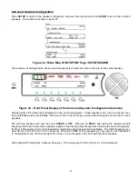
. Figure 13 below shows
INPUT
SELECT
1
having the CD and DVD
input jacks mapped to it, with the CD jack having the highest priority (being in the first position). In this example, there
are no other physical input jacks required to be mapped to
INPUT
SELECT
1
, therefore the jack name for position 3 is
blank. Pressing the
A-D
button while in the
INPUT SELECT
page, will toggle between the CD input jack and the DVD
input jack
Figure 16 - Front Panel Display of the SETUP/INP
page 2
/SOURCE/AUD page
Caution
: Please take special care to insert only a digital signal into a digital input jack and an analog signal only into an
analog input jack. Damage, not covered under warranty, can occur if an analog signal is applied to a digital input.
Additionally, please ensure that a video plug is not inadvertently inserted into a digital audio jack and vice versa,
otherwise, the Casablanca IV will cease to respond.
Summary of Contents for Casablanca IV
Page 2: ...THETA DIGITAL Casablanca IV Owner s Manual V 4 02 Digital Done Right...
Page 17: ...16 Figure 8 All Superior II D A Card Options...
Page 20: ...19...
Page 22: ...21...
Page 31: ...30 Flowchart A Setup Subwoofer s...
Page 32: ...31 Flowchart B Front Left Right Configuration...
Page 33: ...32...
Page 35: ...34 Flowchart F Setup Speaker Levels...
Page 36: ...35 Flowchart H Setup Speaker Delays...
Page 37: ...36 Flowchart I Setup Dolby Digital...
Page 38: ...37 Flowchart J Setup DTS For 7 1 system Set additional Speaker Process Step 13h...
Page 39: ...38 Flowchart K Copy Input Speaker Parameters...
Page 40: ...39 Flowchart L Setup Default Mode...
Page 41: ...40 Flowchart M Map Input Jacks...
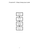
Page 42: ...41 Flowchart N Setup Analog Input Levels...
Page 80: ...79 REMOTE CONTROL...
Page 81: ...80 Figure 59 Remote Control Button Layout...
Page 85: ...84 APPENDIXES...
Page 88: ...87 Figure 62 Recommended Output Wiring Diagram Using 8 balanced Xtreme channels...
Page 89: ...88 Six Shooter Wiring Diagram Figure 63 Wiring diagram for the optional Six Shooter...


